6 `Sm` Machine Extensions
This chapter is currently being restructured. Its contents are normative, but the presentation might appear disjoint.
6.1 Smstateen and Ssstateen Extensions
The implementation of optional RISC-V extensions has the potential to open covert channels between separate user threads, or between separate guest OSes running under a hypervisor. The problem occurs when an extension adds processor state — usually explicit registers, but possibly other forms of state — that the main OS or hypervisor is unaware of (and hence won’t context-switch) but that can be modified/written by one user thread or guest OS and perceived/examined/read by another.
For example, the Advanced Interrupt Architecture (AIA) for RISC-V adds
to a hart as many as ten supervisor-level CSRs (siselect, sireg, stopi,
sseteipnum, sclreipnum, sseteienum, sclreienum, sclaimei, sieh, and siph) and
provides also the option for hardware to be backward-compatible with older,
pre-AIA software. Because an older hypervisor that is oblivious to the AIA will
not know to swap any of the AIA’s new CSRs on context switches, the registers may
then be used as a covert channel between multiple guest OSes that run atop this
hypervisor. Although traditional practices might consider such a communication
channel harmless, the intense focus on security today argues that a means be
offered to plug such channels.
The f registers of the RISC-V floating-point extensions and the v registers of
the vector extension would similarly be potential covert channels between user
threads, except for the existence of the FS and VS fields in the sstatus
register. Even if an OS is unaware of, say, the vector extension and its v
registers, access to those registers is blocked when the VS field is
initialized to zero, either at machine level or by the OS itself initializing
sstatus.
Obviously, one way to prevent the use of new user-level CSRs as covert channels
would be to add to mstatus or sstatus an XS field for each relevant
extension, paralleling the V extension’s VS field. However, this is not
considered a general solution to the problem due to the number of potential
future extensions that may add small amounts of state. Even with a 64-bit
sstatus (necessitating adding sstatush for RV32), it is not certain there are
enough remaining bits in sstatus to accommodate all future user-level
extensions. In any event, there is no need to strain sstatus (and add sstatush)
for this purpose. The enable flags that are needed to plug covert channels
are not generally expected to require swapping on context switches of user
threads, making them a less-than-compelling candidate for inclusion in sstatus.
Hence, a new place is provided for them instead.
6.1.1 State Enable Extensions
The Smstateen and Ssstateen extensions collectively specify machine-mode and supervisor-mode features. The Smstateen extension specification comprises the mstateen*, sstateen*, and hstateen* CSRs and their functionality. The Ssstateen extension specification comprises only the sstateen* and hstateen* CSRs and their functionality.
For RV64 harts, this extension adds four new 64-bit CSRs at machine level:
mstateen0 (Machine State Enable 0), mstateen1, mstateen2, and mstateen3.
If supervisor mode is implemented, another four CSRs are defined at supervisor
level:
sstateen0, sstateen1, sstateen2, and sstateen3.
And if the hypervisor extension is implemented, another set of CSRs is added:
hstateen0, hstateen1, hstateen2, and hstateen3.
For RV32, there are CSR addresses for accessing the upper 32 bits of
corresponding machine-level and hypervisor CSRs:
mstateen0h, mstateen1h, mstateen2h, mstateen3h,
hstateen0h, hstateen1h, hstateen2h, and hstateen3h.
For the supervisor-level sstateen registers, high-half CSRs are not added at
this time because it is expected the upper 32 bits of these registers will
always be zeros, as explained later below.
Each bit of a stateen CSR controls less-privileged access to an extension’s
state, for an extension that was not deemed worthy of a full XS field in
sstatus like the FS and VS fields for the F and V extensions. The number of
registers provided at each level is four because it is believed that 4 * 64 =
256 bits for machine and hypervisor levels, and 4 * 32 = 128 bits for
supervisor level, will be adequate for many years to come, perhaps for as long
as the RISC-V ISA is in use. The exact number four is an attempted compromise
between providing too few bits on the one hand and going overboard with CSRs
that will never be used on the other. A possible future doubling of the number
of stateen CSRs is covered later.
The stateen registers at each level control access to state at all
less-privileged levels, but not at its own level. This is analogous to how the
existing counteren CSRs control access to performance counter registers.
Just as with the counteren CSRs,
when a stateen CSR prevents access to state by
less-privileged levels, an attempt in one of those privilege modes to execute
an instruction that would read or write the protected state raises an illegal-instruction
exception, or, if executing in VS or VU mode and the circumstances
for a virtual-instruction exception apply, raises a virtual-instruction
exception instead of an illegal-instruction exception.
When this extension is not implemented, all state added by an extension is accessible as defined by that extension.
When a stateen CSR prevents access to state for a privilege mode, attempting to
execute in that privilege mode an instruction that implicitly updates the
state without reading it may or may not raise an illegal-instruction or virtual-instruction
exception. Such cases must be disambiguated by being explicitly
specified one way or the other.
In some cases, the bits of the stateen CSRs will have a dual purpose as enables
for the ISA extensions that introduce the controlled state.
Each bit of a supervisor-level sstateen CSR controls user-level access (from
U-mode or VU-mode) to an extension’s state. The intention is to allocate the
bits of sstateen CSRs starting at the least-significant end, bit 0, through to
bit 31, and then on to the next-higher-numbered sstateen CSR.
For every bit with a defined purpose in an sstateen CSR, the same bit is
defined in the matching mstateen CSR to control access below machine level to
the same state. The upper 32 bits of an mstateen CSR (or for RV32, the
corresponding high-half CSR) control access to state that is inherently
inaccessible to user level, so no corresponding enable bits in the
supervisor-level sstateen CSR are applicable. The intention is to allocate bits
for this purpose starting at the most-significant end, bit 63, through to bit
32, and then on to the next-higher mstateen CSR. If the rate that bits are
being allocated from the least-significant end for sstateen CSRs is
sufficiently low, allocation from the most-significant end of mstateen CSRs may
be allowed to encroach on the lower 32 bits before jumping to the next-higher
mstateen CSR. In that case, the bit positions of encroaching bits will remain
forever read-only zeros in the matching sstateen CSRs.
With the hypervisor extension, the hstateen CSRs have identical encodings to
the mstateen CSRs, except controlling accesses for a virtual machine (from VS
and VU modes).
Each standard-defined bit of a stateen CSR is WARL and may be read-only zero or
one, subject to the following conditions.
Bits in any stateen CSR that are defined to control state that a hart doesn’t
implement are read-only zeros for that hart. Likewise, all reserved bits not
yet given a defined meaning are also read-only zeros.
For every bit in an mstateen CSR that is zero
(whether read-only zero or set to zero), the same bit appears as read-only zero in the
matching hstateen and sstateen CSRs.
For every bit in an hstateen CSR that is zero
(whether read-only zero or set to zero), the same bit appears as read-only zero in
sstateen when accessed in VS-mode.
A bit in a supervisor-level sstateen CSR cannot be read-only one unless the
same bit is read-only one in the matching mstateen CSR and, if it exists, in
the matching hstateen CSR. A bit in an hstateen CSR cannot be read-only one
unless the same bit is read-only one in the matching mstateen CSR.
On reset, all writable mstateen bits are initialized by the hardware to zeros.
If machine-level software changes these values, it is responsible for
initializing the corresponding writable bits of the hstateen and sstateen CSRs
to zeros too. Software at each privilege level should set its respective
stateen CSRs to indicate the state it is prepared to allow less-privileged
software to access. For OSes and hypervisors, this usually means the state that
the OS or hypervisor is prepared to swap on a context switch, or to manage in
some other way.
For each mstateen CSR, bit 63 is defined to control access to the
matching sstateen and hstateen CSRs. That is, bit 63 of mstateen0 controls
access to sstateen0 and hstateen0; bit 63 of mstateen1 controls access to
sstateen1 and hstateen1; etc. Likewise, bit 63 of each hstateen
correspondingly controls access to the matching sstateen CSR.
A hypervisor may need this control over accesses to the sstateen CSRs if it
ever must emulate for a virtual machine an extension that is supposed to be
affected by a bit in an sstateen CSR. Even if such emulation is uncommon,
it should not be excluded.
Machine-level software needs identical control to be able to emulate the
hypervisor extension. That is, machine level needs control over accesses to the
supervisor-level sstateen CSRs in order to emulate the hstateen CSRs, which
have such control.
Bit 63 of each mstateen CSR may be read-only zero only if the hypervisor
extension is not implemented and the matching supervisor-level sstateen CSR is
all read-only zeros. In that case, machine-level software should emulate
attempts to access the affected sstateen CSR from S-mode, ignoring writes and
returning zero for reads. Bit 63 of each hstateen CSR is always writable (not
read-only).
6.1.2 State Enable 0 Registers


The C bit controls access to any and all custom state.
The C bit of these registers is not custom state itself; it is a
standard field of a standard CSR, either mstateen0, hstateen0, or
sstateen0.
The requirements that non-standard extensions must meet to be conforming are not relaxed due solely to changes in the value of this bit. In particular, if software sets this bit but does not execute any custom instructions or access any custom state, the software must continue to execute as specified by all relevant RISC-V standards, or the hardware is not standard-conforming.
The FCSR bit controls access to fcsr for the case when floating-point
instructions operate on x registers instead of f registers as specified by
the Zfinx and related extensions (Zdinx, etc.). Whenever misa.F = 1, FCSR bit
of mstateen0 is read-only zero (and hence read-only zero in hstateen0 and
sstateen0 too). For convenience, when the stateen CSRs are implemented and
misa.F = 0, then if the FCSR bit of a controlling stateen0 CSR is zero, all
floating-point instructions cause an illegal-instruction exception (or virtual-instruction
exception, if relevant), as though they all access fcsr, regardless of
whether they really do.
The JVT bit controls access to the jvt CSR provided by the Zcmt extension.
See Section 6.8 for the definition of the CTR bits in mstateen0 and
hstateen0.
The SE0 bit in mstateen0 controls access to the hstateen0, hstateen0h,
and the sstateen0 CSRs. The SE0 bit in hstateen0 controls access to the
sstateen0 CSR.
The ENVCFG bit in mstateen0 controls access to the henvcfg, henvcfgh,
and the senvcfg CSRs. The ENVCFG bit in hstateen0 controls access to the
senvcfg CSRs.
The CSRIND bit in mstateen0 controls access to the siselect, sireg*,
vsiselect, and the vsireg* CSRs provided by the Sscsrind extensions.
The CSRIND bit in hstateen0 controls access to the siselect and the
sireg*, (really vsiselect and vsireg*) CSRs provided by the Sscsrind
extensions.
The IMSIC bit in mstateen0 controls access to the IMSIC state, including
CSRs stopei and vstopei, provided by the Ssaia extension. The IMSIC bit in
hstateen0 controls access to the guest IMSIC state, including CSRs stopei
(really vstopei), provided by the Ssaia extension.
Setting the IMSIC bit in hstateen0 to zero prevents a virtual machine from
accessing the hart’s IMSIC the same as setting hstatus.VGEIN = 0.
The AIA bit in mstateen0 controls access to all state introduced by the
Ssaia extension and not controlled by either the CSRIND or the IMSIC
bits. The AIA bit in hstateen0 controls access to all state introduced by the
Ssaia extension and not controlled by either the CSRIND or the IMSIC
bits of hstateen0.
The CONTEXT bit in mstateen0 controls access to the scontext and
hcontext CSRs provided by the Sdtrig extension. The CONTEXT bit in
hstateen0 controls access to the scontext CSR provided by the Sdtrig
extension.
The P1P13 bit in mstateen0 controls access to the hedelegh introduced by
Privileged Specification Version 1.13.
The SRMCFG bit in mstateen0 controls access to the srmcfg CSR introduced by
the Ssqosid Section 8.1 extension.
6.1.3 Usage
After the writable bits of the machine-level mstateen CSRs are initialized to
zeros on reset, machine-level software can set bits in these registers to
enable less-privileged access to the controlled state. This may be either
because machine-level software knows how to swap the state or, more likely,
because machine-level software isn’t swapping supervisor-level environments.
(Recall that the main reason the mstateen CSRs must exist is so machine level
can emulate the hypervisor extension. When machine level isn’t emulating the
hypervisor extension, it is likely there will be no need to keep any
implemented mstateen bits zero.)
If machine level sets any writable mstateen bits to nonzero, it must initialize
the matching hstateen CSRs, if they exist, by writing zeros to them. And if any
mstateen bits that are set to one have matching bits in the sstateen CSRs,
machine-level software must also initialize those sstateen CSRs by writing
zeros to them. Ordinarily, machine-level software will want to set bit 63 of
all mstateen CSRs, necessitating that it write zero to all hstateen CSRs.
Software should ensure that all writable bits of sstateen CSRs are initialized
to zeros when an OS at supervisor level is first entered. The OS can then set
bits in these registers to enable user-level access to the controlled state,
presumably because it knows how to context-swap the state.
For the sstateen CSRs whose access by a guest OS is permitted by bit 63 of the
corresponding hstateen CSRs, a hypervisor must include the sstateen CSRs in the
context it swaps for a guest OS. When it starts a new guest OS, it must ensure
the writable bits of those sstateen CSRs are initialized to zeros, and it must
emulate accesses to any other sstateen CSRs.
If software at any privilege level does not support multiple contexts for
less-privilege levels, then it may choose to maximize less-privileged access to
all state by writing a value of all ones to the stateen CSRs at its level (the
mstateen CSRs for machine level, the sstateen CSRs for an OS, and the hstateen
CSRs for a hypervisor), without knowing all the state to which it is granting
access. This is justified because there is no risk of a covert channel between
execution contexts at the less-privileged level when only one context exists
at that level. This situation is expected to be common for machine level, and
it might also arise, for example, for a type-1 hypervisor that hosts only a
single guest virtual machine.
If a need is anticipated, the set of stateen CSRs could in the future be
doubled by adding these:
0x38C mstateen4,0x39C mstateen4h0x38D mstateen5,0x39D mstateen5h0x38E mstateen6,0x39E mstateen6h0x38F mstateen7,0x39F mstateen7h0x18C sstateen40x18D sstateen50x18E sstateen60x18F sstateen70x68C hstateen4,0x69C hstateen4h0x68D hstateen5,0x69D hstateen5h0x68E hstateen6,0x69E hstateen6h0x68F hstateen7,0x69F hstateen7h
These additional CSRs are not a definite part of the original proposal because
it is unclear whether they will ever be needed, and it is believed the rate of
consumption of bits in the first group, registers numbered 0-3, will be slow
enough that any looming shortage will be perceptible many years in advance. At
the moment, it is not known even how many years it may take to exhaust just
mstateen0, sstateen0, and hstateen0.
6.2 Smcsrind and Sscsrind Extensions for Indirect CSR Access
6.2.1 Introduction
Smcsrind/Sscsrind is an ISA extension that extends the indirect CSR access mechanism originally defined as part of the Smaia/Ssaia extensions, in order to make it available for use by other extensions without creating an unnecessary dependence on Smaia/Ssaia.
This extension confers two benefits:
- It provides a means to access an array of registers via CSRs without requiring allocation of large chunks of the limited CSR address space.
- It enables software to access each of an array of registers by index, without requiring a switch statement with a case for each register.
CSRs are accessed indirectly via this extension using select values, in contrast to being accessed directly using standard CSR numbers. A CSR accessible via one method may or may not be accessible via the other method. Select values are a separate address space from CSR numbers, and from tselect values in the Sdtrig extension. If a CSR is both directly and indirectly accessible, the CSR’s select value is unrelated to its CSR number.
Further, Machine-level and Supervisor-level select values are separate address spaces from each other; however, Machine-level and Supervisor-level CSRs with the same select value may be defined by an extension as partial or full aliases with respect to each other. This typically would be done for CSRs that can be delegated from Machine-level to Supervisor-level.
The machine-level extension Smcsrind encompasses all added CSRs and all behavior modifications for a hart, over all privilege levels. For a supervisor-level environment, extension Sscsrind is essentially the same as Smcsrind except excluding the machine-level CSRs and behavior not directly visible to supervisor level.
6.2.2 Machine-level CSRs
| Number | Privilege | Width | Name | Description |
|---|---|---|---|---|
| 0x350 | MRW | XLEN | miselect | Machine indirect register select |
| 0x351 | MRW | XLEN | mireg | Machine indirect register alias |
| 0x352 | MRW | XLEN | mireg2 | Machine indirect register alias 2 |
| 0x353 | MRW | XLEN | mireg3 | Machine indirect register alias 3 |
| 0x355 | MRW | XLEN | mireg4 | Machine indirect register alias 4 |
| 0x356 | MRW | XLEN | mireg5 | Machine indirect register alias 5 |
| 0x357 | MRW | XLEN | mireg6 | Machine indirect register alias 6 |
The mireg* CSR numbers are not consecutive because miph is CSR number
0x354.
The CSRs listed in the table above provide a window for accessing
register state indirectly. The value of miselect determines which
register is accessed upon read or write of each of the machine indirect alias
CSRs (mireg*). miselect value ranges are allocated to dependent
extensions, which specify the register state accessible via each
mireg_i_ register, for each miselect value. miselect is a WARL
register.
The miselect register implements at least enough bits to support all
implemented miselect values (corresponding to the implemented extensions
that utilize miselect/mireg* to indirectly access register state). The
miselect register may be read-only zero if there are no extensions
implemented that utilize it.
Values of miselect with the most-significant bit set (bit XLEN - 1 = 1)
are designated only for custom use, presumably for accessing custom
registers through the alias CSRs. Values of miselect with the
most-significant bit clear are designated only for standard use and are
reserved until allocated to a standard architecture extension. If XLEN
is changed, the most-significant bit of miselect moves to the new
position, retaining its value from before.
An implementation is not required to support any custom values for
miselect.
The behavior upon accessing mireg* from M-mode, while miselect holds a
value that is not implemented, is UNSPECIFIED.
It is expected that implementations will typically raise an illegal-instruction exception for such accesses, so that, for example, they can be identified as software bugs. Platform specs, profile specs, and/or the Privileged ISA spec may place more restrictions on behavior for such accesses.
Attempts to access mireg* while miselect holds a number in an allocated
and implemented range results in a specific behavior that, for each
combination of miselect and mireg_i_, is defined by the extension to
which the miselect value is allocated.
Ordinarily, each miregi will access register state, access
read-only 0 state, or raise an illegal-instruction exception.
For RV32, if an extension defines an indirectly accessed register as 64 bits wide, it is recommended that the lower 32 bits of the register are accessed through one of mireg, mireg2, or mireg3, while the upper 32 bits are accessed through mireg4, mireg5, or mireg6, respectively.
Six *ireg* registers are defined in order to ensure that the needs of extensions in development are covered, with some room for growth. For example, for an siselect value associated with counter X, sireg/sireg2 could be used to access mhpmcounterX/mhpmeventX, while sireg4/sireg5 could access mhpmcounterXh/mhpmeventXh. Six *ireg* registers allows for accessing up to 3 CSR arrays per index (*iselect) with RV32-only CSRs, or up to 6 CSR arrays per index value without RV32-only CSRs.
6.2.3 Supervisor-level CSRs
| Number | Privilege | Width | Name | Description |
|---|---|---|---|---|
| 0x150 | SRW | XLEN | siselect | Supervisor indirect register select |
| 0x151 | SRW | XLEN | sireg | Supervisor indirect register alias |
| 0x152 | SRW | XLEN | sireg2 | Supervisor indirect register alias 2 |
| 0x153 | SRW | XLEN | sireg3 | Supervisor indirect register alias 3 |
| 0x155 | SRW | XLEN | sireg4 | Supervisor indirect register alias 4 |
| 0x156 | SRW | XLEN | sireg5 | Supervisor indirect register alias 5 |
| 0x157 | SRW | XLEN | sireg6 | Supervisor indirect register alias 6 |
The CSRs in the table above are required if S-mode is implemented.
The siselect register will support the value range 0..0xFFF at a
minimum. A future extension may define a value range outside of this
minimum range. Only if such an extension is implemented will siselect be
required to support larger values.
Requiring a range of 0–0xFFF for siselect, even though most or
all of the space may be reserved or inaccessible, permits M-mode to
emulate indirectly accessed registers in this implemented range,
including registers that may be standardized in the future.
Values of siselect with the most-significant bit set (bit XLEN - 1 = 1)
are designated only for custom use, presumably for accessing custom registers through the alias
CSRs. Values of siselect with the most-significant bit clear are
designated only for standard use and are reserved until allocated to a
standard architecture extension. If XLEN is changed, the
most-significant bit of siselect moves to the new position, retaining
its value from before.
The behavior upon accessing sireg* from M-mode or S-mode, while siselect
holds a value that is not implemented at supervisor level, is UNSPECIFIED.
It is recommended that implementations raise an illegal-instruction exception for such accesses, to facilitate possible emulation (by M-mode) of these accesses.
An extension is considered not to be implemented at supervisor level if
machine level has disabled the extension for S-mode, such as by the
settings of certain fields in CSR menvcfg, for example.
Otherwise, attempts to access sireg* from M-mode or S-mode while
siselect holds a number in a standard-defined and implemented range
result in specific behavior that, for each combination of siselect and
sireg_i_, is defined by the extension to which the siselect value is
allocated.
Ordinarily, each siregi will access register state, access
read-only 0 state, or, unless executing in a virtual machine (covered in
the next section), raise an illegal-instruction exception.
Note that the widths of siselect and sireg* are always the
current XLEN rather than SXLEN. Hence, for example, if MXLEN = 64 and
SXLEN = 32, then these registers are 64 bits when the current privilege
mode is M (running RV64 code) but 32 bits when the privilege mode is S
(RV32 code).
6.2.4 Virtual Supervisor-level CSRs
| Number | Privilege | Width | Name | Description |
|---|---|---|---|---|
| 0x250 | HRW | XLEN | vsiselect | Virtual supervisor indirect register select |
| 0x251 | HRW | XLEN | vsireg | Virtual supervisor indirect register alias |
| 0x252 | HRW | XLEN | vsireg2 | Virtual supervisor indirect register alias 2 |
| 0x253 | HRW | XLEN | vsireg3 | Virtual supervisor indirect register alias 3 |
| 0x255 | HRW | XLEN | vsireg4 | Virtual supervisor indirect register alias 4 |
| 0x256 | HRW | XLEN | vsireg5 | Virtual supervisor indirect register alias 5 |
| 0x257 | HRW | XLEN | vsireg6 | Virtual supervisor indirect register alias 6 |
The CSRs in the table above are required if the hypervisor extension is implemented. These VS CSRs all match supervisor CSRs, and substitute for those supervisor CSRs when executing in a virtual machine (in VS-mode or VU-mode).
The vsiselect register will support the value range 0..0xFFF at a
minimum. A future extension may define a value range outside of this
minimum range. Only if such an extension is implemented will vsiselect
be required to support larger values.
Requiring a range of 0–0xFFF for vsiselect, even though most or all of
the space may be reserved or inaccessible, permits a hypervisor to
emulate indirectly accessed registers in this implemented range,
including registers that may be standardized in the future.
More generally it is recommended that vsiselect and siselect be
implemented with the same number of bits. This also avoids creation of a
virtualization hole due to observable differences between vsiselect and
siselect widths.
Values of vsiselect with the most-significant bit set (bit XLEN - 1 = 1)
are designated only for custom use, presumably for accessing custom registers through the alias
CSRs. Values of vsiselect with the most-significant bit clear are
designated only for standard use and are reserved until allocated to a
standard architecture extension. If XLEN is changed, the
most-significant bit of vsiselect moves to the new position, retaining
its value from before.
For alias CSRs sireg* and vsireg*, the hypervisor extension’s usual
rules for when to raise a virtual-instruction exception (based on
whether an instruction is HS-qualified) are not applicable. The
rules given in this section for sireg and vsireg apply instead, unless
overridden by the requirements specified in the section below, which
take precedence over this section when extension Smstateen is also
implemented.
A virtual-instruction exception is raised for attempts from VS-mode or VU-mode to directly access vsiselect or vsireg*, or attempts from VU-mode to access siselect or sireg*.
The behavior upon accessing vsireg* from M-mode or HS-mode, or accessing sireg* (really vsireg*) from VS-mode, while vsiselect holds a value that is not implemented at HS level, is UNSPECIFIED.
It is recommended that implementations raise an illegal-instruction exception for such accesses, to facilitate possible emulation (by M-mode) of these accesses.
Otherwise, while vsiselect holds a number in a standard-defined and
implemented range, attempts to access vsireg* from a sufficiently
privileged mode, or to access sireg* (really vsireg*) from VS-mode,
result in specific behavior that, for each combination of vsiselect and
vsireg_i_, is defined by the extension to which the vsiselect value is
allocated.
Ordinarily, each vsiregi will access register state, access read-only 0 state, or raise an exception (either an illegal-instruction exception or, for select accesses from VS-mode, a virtual-instruction exception). When vsiselect holds a value that is implemented at HS level but not at VS level, attempts to access sireg* (really vsireg*) from VS-mode will typically raise a virtual-instruction exception. But there may be cases specific to an extension where different behavior is more appropriate.
Like siselect and sireg*, the widths of vsiselect and vsireg* are always
the current XLEN rather than VSXLEN. Hence, for example, if HSXLEN = 64
and VSXLEN = 32, then these registers are 64 bits when accessed by a
hypervisor in HS-mode (running RV64 code) but 32 bits for a guest OS in
VS-mode (RV32 code).
6.2.5 Access control by the state-enable CSRs
If extension Smstateen is implemented together with Smcsrind, bit 60 of
state-enable register mstateen0 controls access to siselect, sireg*,
vsiselect, and vsireg*. When mstateen0[60]=0, an attempt to access one
of these CSRs from a privilege mode less privileged than M-mode results
in an illegal-instruction exception. As always, the state-enable CSRs do
not affect the accessibility of any state when in M-mode, only in less
privileged modes. For more explanation, see the documentation for
extension Smstateen in Section 6.1.
Other extensions may specify that certain mstateen bits control access
to registers accessed indirectly through siselect + sireg*, and/or
vsiselect + vsireg*. However, regardless of any other mstateen bits, if
mstateen0[60] = 1, a virtual-instruction exception is raised as
described in the previous section for all attempts from VS-mode or
VU-mode to directly access vsiselect or vsireg*, and for all attempts
from VU-mode to access siselect or sireg*.
If the hypervisor extension is implemented, the same bit is defined also
in hypervisor CSR hstateen0, but controls access to only siselect and sireg*
(really vsiselect and vsireg*), which is the state potentially
accessible to a virtual machine executing in VS or VU-mode. When
hstateen0[60]=0 and mstateen0[60]=1, all attempts from VS or VU-mode to
access siselect or sireg* raise a virtual-instruction exception, not an
illegal-instruction exception, regardless of the value of vsiselect or
any other mstateen bit.
Extension Ssstateen is defined as the supervisor-level view of
Smstateen. Therefore, the combination of Sscsrind and Ssstateen
incorporates the bit defined above for hstateen0 but not that for
mstateen0, since machine-level CSRs are not visible to supervisor level.
CSR address space is reserved for a possible future Sucsrind extension that extends indirect CSR access to user mode.
6.3 Smepmp Extension for PMP Enhancements for memory access and execution prevention in Machine mode
Being able to access the memory of a process running at a high privileged execution mode, such as the Supervisor or Machine mode, from a lower privileged mode such as the User mode, introduces an obvious attack vector since it allows for an attacker to perform privilege escalation, and tamper with the code and/or data of that process. A less obvious attack vector exists when the reverse happens, in which case an attacker instead of tampering with code and/or data that belong to a high-privileged process, can tamper with the memory of an unprivileged / less-privileged process and trick the high-privileged process to use or execute it.
Two mechanisms combine to prevent this attack vector.
The first one prevents the OS from accessing the memory of an unprivileged
process unless a specific code path is followed, and the second one prevents
the OS from executing the memory of an unprivileged process at all times.
RISC-V already includes support for the former through the sstatus.SUM bit,
and for the latter by always denying supervisor execution of virtual memory
pages marked with the U bit.
Terms:
- PMP Entry: A pair of
pmpcfg[i]/pmpaddr[i]registers. - PMP Rule: The contents of a pmpcfg register and its associated pmpaddr register(s), that encode a valid protected physical memory region, where
pmpcfg[i].A != OFF, and ifpmpcfg[i].A == TOR,pmpaddr[i-1] \< pmpaddr[i]. - Ignored: Any permissions set by a matching PMP rule are ignored, and all accesses to the requested address range are allowed.
- Enforced: Only access types configured in the PMP rule matching the requested address range are allowed; failures will cause an access-fault exception.
- Denied: Any permissions set by a matching PMP rule are ignored, and no accesses to the requested address range are allowed.; failures will cause an access-fault exception.
- Locked: A PMP rule/entry where the
pmpcfg.Lbit is set. - PMP reset: A reset process where all PMP settings of the hart, including locked rules/settings, are re-initialized to a set of safe defaults, before releasing the hart (back) to the firmware / OS / application.
6.3.1 Threat model
The rationale that guided development of this extension is included in Section Section A.1.
Without the Smepmp extension, it is not possible for a PMP rule to be enforced only on non-Machine modes and denied on Machine mode, in order to allow access to a memory region solely by less-privileged modes. It is only possible to have a locked rule that will be enforced on all modes, or a rule that will be enforced on non-Machine modes and be ignored by Machine mode. So for any physical memory region which is not protected with a Locked rule, Machine mode has unlimited access, including the ability to execute it.
Without being able to protect less-privileged modes from Machine mode, it is not possible to prevent the mentioned attack vector. This becomes even more important for RISC-V than on other architectures, since implementations are allowed where a hart only has Machine and User modes available, so the whole OS will run on Machine mode instead of the non-existent Supervisor mode. In such implementations the attack surface is greatly increased, and the same kind of attacks performed on Supervisor mode and mitigated through the virtual-memory system, can be performed on Machine mode without any available mitigations. Even on implementations with Supervisor mode present attacks are still possible against the Firmware and/or the Secure Monitor running on Machine mode.
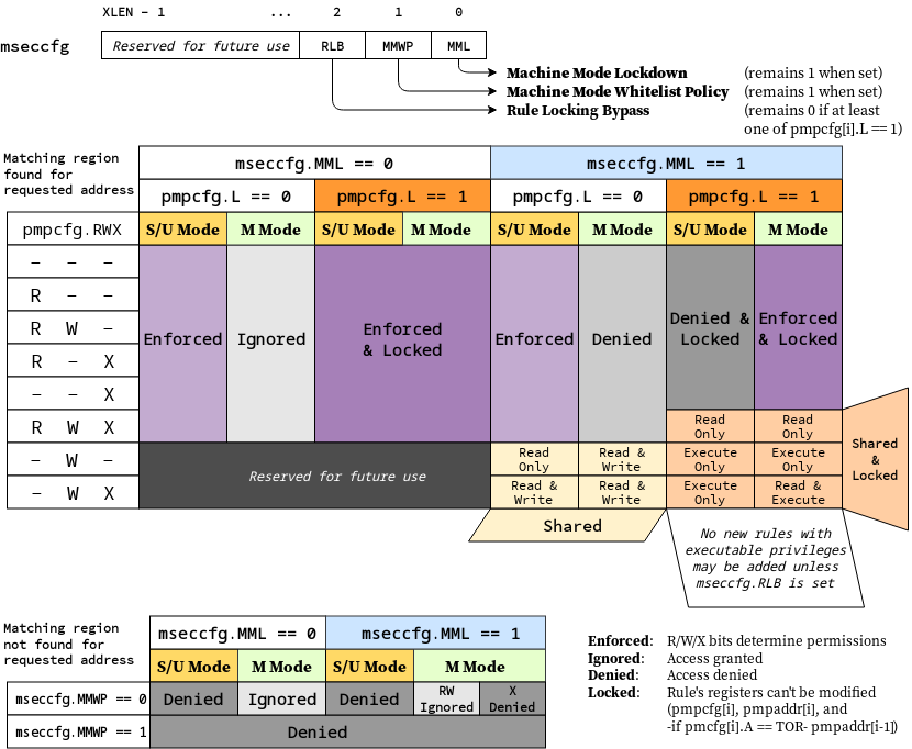
6.3.2 Smepmp Physical Memory Protection Rules
To address the threat model outlined in Section Section 6.3.1, this
extension introduces the RLB, MMWP, and MML fields in the mseccfg CSR
and their associated rules. See Machine security configuration (mseccfg) register. for the detailed
specification of these fields and the corresponding rules.
The physical memory protection rules when mseccfg.MML is set to 1 are summarized in the truth table below.
| Bits on pmpcfg register | Result | ||||
|---|---|---|---|---|---|
| L | R | W | X | M Mode | S/U Mode |
| 0 | 0 | 0 | 0 | Inaccessible region (Access Exception) | |
| 0 | 0 | 0 | 1 | Access Exception | Execute-only region |
| 0 | 0 | 1 | 0 | Shared data region: Read/write on M mode, read-only on S/U mode | |
| 0 | 0 | 1 | 1 | Shared data region: Read/write for both M and S/U mode | |
| 0 | 1 | 0 | 0 | Access Exception | Read-only region |
| 0 | 1 | 0 | 1 | Access Exception | Read/Execute region |
| 0 | 1 | 1 | 0 | Access Exception | Read/Write region |
| 0 | 1 | 1 | 1 | Access Exception | Read/Write/Execute region |
| 1 | 0 | 0 | 0 | Locked inaccessible region* (Access Exception) | |
| 1 | 0 | 0 | 1 | Locked Execute-only region* | Access Exception |
| 1 | 0 | 1 | 0 | Locked Shared code region: Execute only on both M and S/U mode.* | |
| 1 | 0 | 1 | 1 | Locked Shared code region: Execute only on S/U mode, read/execute on M mode.* | |
| 1 | 1 | 0 | 0 | Locked Read-only region* | Access Exception |
| 1 | 1 | 0 | 1 | Locked Read/Execute region* | Access Exception |
| 1 | 1 | 1 | 0 | Locked Read/Write region* | Access Exception |
| 1 | 1 | 1 | 1 | Locked Shared data region: Read only on both M and S/U mode.* | |
*: Locked rules cannot be removed or modified until a PMP reset, unless mseccfg.RLB is set.
A visual representation of these rules is as follows:
6.3.3 Smepmp software discovery
Since all fields defined in mseccfg as part of this extension are locked when set (MMWP/MML) or locked when cleared (RLB), software can’t poll them for determining the presence of Smepmp. It is expected that BootROM will set mseccfg.MMWP and/or mseccfg.MML during early boot, before jumping to the firmware, so that the firmware will be able to determine the presence of Smepmp by reading mseccfg and checking the state of mseccfg.MMWP and mseccfg.MML.
6.4 Smcntrpmf Cycle and Instret Privilege Mode Filtering
6.4.1 Introduction
The cycle and instret counters serve to support user mode self-profiling usages, wherein a user can read the counter(s) twice and compute the delta(s) to evaluate user software performance and behavior. By default, these counters are not filtered by privilege mode, and thus they continue to increment while traps (e.g., page faults or interrupts) to more privileged code are handled. This causes two problems:
- It introduces unpredictable noise to the counter values observed by the user.
- It leaks information about privileged software execution to user mode.
Smcntrpmf remedies these issues by introducing privilege mode filtering for the cycle and instret counters.
6.4.2 CSRs
6.4.2.1 Machine Counter Configuration (mcyclecfg, minstretcfg) Registers
mcyclecfg and minstretcfg are 64-bit registers that configure privilege mode filtering for the cycle and instret counters, respectively.
| 63 | 62 | 61 | 60 | 59 | 58 | 57:0 |
|---|---|---|---|---|---|---|
| 0 | MINH | SINH | UINH | VSINH | VUINH | WPRI |
| Field | Description |
|---|---|
| MINH | If set, then counting of events in M-mode is inhibited |
| SINH | If set, then counting of events in S/HS-mode is inhibited |
| UINH | If set, then counting of events in U-mode is inhibited |
| VSINH | If set, then counting of events in VS-mode is inhibited |
| VUINH | If set, then counting of events in VU-mode is inhibited |
When all _x_INH bits are zero, event counting is enabled in all modes.
For each bit in 61:58, if the associated privilege mode is not implemented, the bit is read-only zero.
For RV32, bits 63:32 of mcyclecfg can be accessed via the mcyclecfgh CSR, and bits 63:32 of minstretcfg can be accessed via the minstretcfgh CSR.
The content of these registers may be accessible from Supervisor level if the Smcdeleg/Ssccfg extensions are implemented.
The more natural CSR number for mcyclecfg would be 0x320, but that was allocated to mcountinhibit.
This register format matches that specified for programmable counters by Sscofpmf. The bit position for the OF bit (bit 63) is read-only 0, since these counters do not generate local-counter-overflow interrupts on overflow.
6.4.3 Counter Behavior
The fundamental behavior of cycle and instret is modified in that counting does not occur while executing in an inhibited privilege mode. Further, the following defines how transitions between a non-inhibited privilege mode and an inhibited privilege mode are counted.
The cycle counter will simply count CPU cycles while the CPU is in a non-inhibited privilege mode. Mode transition operations (traps and trap returns) may take multiple clock cycles, and the change of privilege mode may be reported as occurring in any one of those cycles (possibly different for each occurrence of a trap or trap return).
The RISC-V ISA has no requirement that the number of cycles for a trap or trap return be the same for all occurrences. Implementations are free to determine the extent to which this number may be consistent and predictable (or not), and the same is true for the specific cycle in which privilege mode changes.
For the instret counter, most instructions do not affect mode transitions, so for those the behavior is clear: instructions that retire in a non-inhibited mode increment instret, and instructions that retire in an inhibited mode do not. There are two types of instructions that can affect a privilege mode change: instructions that cause synchronous exceptions to a more privileged mode, and xRET instructions that return to a less privileged mode. The former are not considered to retire, and hence do not increment instret. The latter do retire, and should increment instret only if the originating privilege mode is not inhibited.
The instret definition above is intended to ensure that the counter increments in a predictable fashion. For example, consider a scenario where minstretcfg is configured such that all modes other than U-mode are inhibited. A user mode load should increment only once, even if it takes a page fault or other exception. With this definition, the faulting execution of the load will not increment (it does not retire), the handler instructions will not increment (they execute in an inhibited mode), including the xRET (it arguably retires in a non-inhibited mode, but it originates in an inhibited mode). Only once the load is re-executed and retires will it increment instret.
In cases where an instruction is emulated by software running in a privilege mode that is inhibited in minstretcfg, the emulation routine must emulate the instret increment.
6.5 Smrnmi Extension for Resumable Non-Maskable Interrupts
The base machine-level architecture supports only unresumable
non-maskable interrupts (UNMIs), where the NMI jumps to a handler in
machine mode, overwriting the current mepc and mcause register
values. If the hart had been executing machine-mode code in a trap
handler, the previous values in mepc and mcause would not be
recoverable and so execution is not generally resumable.
The Smrnmi extension adds support for resumable non-maskable interrupts
(RNMIs) to RISC-V. The extension adds four new CSRs (mnepc, mncause,
mnstatus, and mnscratch) to hold the interrupted state, and one new
instruction, MNRET, to resume from the RNMI handler.
6.5.1 RNMI Interrupt Signals
The rnmi interrupt signals are inputs to the hart. These interrupts
have higher priority than any other interrupt or exception on the hart
and cannot be disabled by software. Specifically, they are not disabled
by clearing the mstatus.MIE register.
6.5.2 RNMI Handler Addresses
The RNMI interrupt trap handler address is implementation-defined.
RNMI also has an associated exception trap handler address, which is implementation defined.
For example, some implementations might use the address specified
in mtvec as the RNMI exception trap handler.
6.5.3 RNMI CSRs
This extension adds additional M-mode CSRs to enable a resumable non-maskable interrupt (RNMI).

The mnscratch CSR holds an MXLEN-bit read-write register which enables
the RNMI trap handler to save and restore the context that was
interrupted.

The mnepc CSR is an MXLEN-bit read-write register which on entry to
the RNMI trap handler holds the PC of the instruction that took the
interrupt.
The low bit of mnepc (mnepc[0]) is always zero. On implementations
that support only IALIGN=32, the two low bits (mnepc[1:0]) are always
zero.
If an implementation allows IALIGN to be either 16 or 32 (by changing
CSR misa, for example), then, whenever IALIGN=32, bit mnepc[1] is
masked on reads so that it appears to be 0. This masking occurs also for
the implicit read by the MNRET instruction. Though masked, mnepc[1]
remains writable when IALIGN=32.
mnepc is a WARL register that must be able to hold all valid virtual
addresses. It need not be capable of holding all possible invalid
addresses. Prior to writing mnepc, implementations may convert an
invalid address into some other invalid address that mnepc is capable
of holding.

The mncause CSR holds the reason for the RNMI.
If the reason is an interrupt, bit MXLEN-1 is set to 1, and the RNMI
cause is encoded in the least-significant bits.
If the reason is an interrupt and RNMI causes are not supported, bit MXLEN-1 is
set to 1, and zero is written to the least-significant bits.
If the reason is an exception within M-mode that results in a double trap as
specified in the Smdbltrp extension, bit MXLEN-1 is set to 0 and the
least-significant bits are set to the cause code corresponding to the
exception that precipitated the double trap.

The mnstatus CSR holds a two-bit field, MNPP, which on entry to the
RNMI trap handler holds the privilege mode of the interrupted context,
encoded in the same manner as mstatus.MPP. If the H extension is also
implemented, mnstatus also holds a one-bit
field, MNPV, which on entry to the RNMI trap handler holds the virtualization
mode of the interrupted context, encoded in the same manner as
mstatus.MPV.
If the Zicfilp extension is implemented, mnstatus also holds the MNPELP
field, which on entry to the RNMI trap handler holds the previous ELP state.
When an RNMI trap is taken, MNPELP is set to ELP and ELP is set to 0.
mnstatus also holds the NMIE bit. When NMIE=1, non-maskable interrupts
are enabled. When NMIE=0, all interrupts are disabled.
When NMIE=0, the hart behaves as though mstatus.MPRV were clear,
regardless of the current setting of mstatus.MPRV.
Upon reset, NMIE contains the value 0.
RNMIs are masked out of reset to give software the opportunity to initialize data structures and devices for subsequent RNMI handling.
Software can set NMIE to 1, but attempts to clear NMIE have no effect.
Normally, only reset sequences will explicitly set the NMIE bit.
That the NMIE bit is settable does not suffice to support the nesting of RNMIs. To support this feature in a direct manner would have required allowing software to clear the NMIE bit—a design choice that would have contravened the concept of non-maskability.
Software that wishes to minimize the latency until the next RNMI is taken can follow the top-half/bottom-half model, where the RNMI handler itself only enqueues a task to a task queue then returns. The bulk of the interrupt servicing is performed later, with RNMIs enabled.
For the purposes of the WFI instruction, NMIE is a global interrupt enable, meaning that the setting of NMIE does not affect the operation of the WFI instruction.
The other bits in mnstatus are reserved; software should write zeros
and hardware implementations should return zeros.
6.5.4 MNRET Instruction
MNRET is an M-mode-only instruction that uses the values in mnepc and
mnstatus to return to the program counter, privilege mode, and
virtualization mode of the interrupted context. This instruction also
sets mnstatus.NMIE. If MNRET changes the privilege mode to a mode less privileged than M, it also sets mstatus.MPRV to 0.
If the Zicfilp extension is implemented, then if the new privileged mode
is y, MNRET sets ELP to the logical AND of _y_LPE (see Section 6.9.1.1) and mnstatus.MNPELP.
6.5.5 RNMI Operation
When an RNMI interrupt is detected, the interrupted PC is written to the
mnepc CSR, the type of RNMI to the mncause CSR, and the privilege
mode of the interrupted context to the mnstatus CSR. The
mnstatus.NMIE bit is cleared, masking all interrupts.
The hart then enters machine-mode and jumps to the RNMI trap handler address.
The RNMI handler can resume original execution using the new MNRET
instruction, which restores the PC from mnepc, the privilege mode from
mnstatus, and also sets mnstatus.NMIE, which re-enables interrupts.
If the hart encounters an exception while executing in M-mode with the mnstatus.NMIE bit clear, the actions taken are the same as if the exception had occurred while mnstatus.NMIE were set, except that the program counter is set to the RNMI exception trap handler address.
The Smrnmi extension does not change the behavior of the MRET and SRET
instructions. In particular, MRET and SRET are unaffected by the
mnstatus.NMIE bit, and their execution does not alter the
mnstatus.NMIE bit.
6.6 Smcdeleg and Ssccfg Counter Delegation Extensions
In modern “Rich OS” environments, hardware performance monitoring resources are managed by the kernel, kernel driver, and/or hypervisor. Counters may be configured with differing scopes, in some cases counting events system-wide, while in others counting events on behalf of a single virtual machine or application. In such environments, the latency of counter writes has a direct impact on overall profiling overhead as a result of frequent counter writes during:
- Sample collection, to clear overflow indication, and reload overflowed counter(s)
- Context switch, between processes, threads, containers, or virtual machines
These extensions provide a means for M-mode to allow writing select counters and event selectors from S/HS-mode. The purpose is to avert transitions to and from M-mode that add latency to these performance critical supervisor/hypervisor code sections. These extensions also defines one new CSR, scountinhibit.
For a Machine-level environment, extension Smcdeleg (‘Sm’ for Privileged architecture and Machine-level extension, ‘cdeleg’ for Counter Delegation) encompasses all added CSRs and all behavior modifications for a hart, over all privilege levels. For a Supervisor-level environment, extension Ssccfg (‘Ss’ for Privileged architecture and Supervisor-level extension, ‘ccfg’ for Counter Configuration) provides access to delegated counters, and to new supervisor-level state.For a RISC-V hardware platform, Smcdeleg and Ssccfg must always be implemented in tandem.
The Smcdeleg and Ssccfg extensions both depend on the Sscsrind extension.
6.6.1 Counter Delegation
The mcounteren register allows M-mode to provide the next-lower
privilege mode with read access to select counters.When the Smcdeleg/Ssccfg extensions are enabled (menvcfg.CDE=1), it further allows M-mode to delegate select counters to S-mode.
The siselect (and vsiselect) index range 0x40-0x5F is reserved for
delegated counter access. When a counter i is delegated
(mcounteren[i]=1 and menvcfg.CDE=1), the register state associated
with counter i can be read or written via sireg*, while siselect holds
0x40+i. The counter state accessible via alias CSRs is shown in
the table below.
Table 45. Indirect HPM State Mappings
siselect value | **sireg** | sireg4 | sireg2 | sireg5 |
|---|---|---|---|---|
| 0x40 | cycle1 | cycleh1 | cyclecfg14 | cyclecfgh14 |
| 0x41 | See below | |||
| 0x42 | instret1 | instreth1 | instretcfg14 | instretcfgh14 |
| 0x43 | hpmcounter32 | hpmcounter3h2 | hpmevent32 | hpmevent3h23 |
| … | … | … | … | … |
| 0x5F | hpmcounter312 | hpmcounter31h2 | hpmevent312 | hpmevent31h23 |
4 Depends on Smcntrpmf support
hpmevent_i_ may represent a subset of the state accessed by the mhpmevent_i_ register. Specifically, if Sscofpmf is implemented, event selector bit
62 (MINH) is read-only 0 when accessed through sireg*.
Likewise, cyclecfg and instretcfg may represent a subset of the state accessed by the mcyclecfg and minstretcfg registers, respectively. If
Smcntrpmf is implemented, counter configuration register bit 62 (MINH) is read-only 0 when accessed through sireg*.
If extension Smstateen is implemented, refer to extensions Smcsrind/Sscsrind (Section 6.2) for how setting bit 60 of CSR
mstateen0 to zero prevents access to registers siselect, sireg*,
vsiselect, and vsireg* from privileged modes less privileged than
M-mode, and likewise how setting bit 60 of hstateen0 to zero prevents
access to siselect and sireg* (really vsiselect and vsireg*) from
VS-mode.
The remaining rules of this section apply only when access to a CSR is
not blocked by mstateen0[60] = 0 or hstateen0[60] = 0.
While the privilege mode is M or S and siselect holds a value in the
range 0x40-0x5F, illegal-instruction exceptions are raised for the
following cases:
- attempts to access any
sireg*whenmenvcfg.CDE = 0; - attempts to access
sireg3orsireg6; - attempts to access
sireg4orsireg5when XLEN = 64; - attempts to access
sireg*whensiselect= 0x41, or when the counter selected bysiselectis not delegated to S-mode (the corresponding bit inmcounteren= 0).
The memory-mapped mtime register is not a performance monitoring
counter to be managed by supervisor software, hence the special
treatment of siselect value 0x41 described above.
For each siselect and sireg* combination defined in Table 45, the table
further indicates the extensions upon which the underlying counter state
depends.If any extension upon which the underlying state depends is not implemented, an attempt from M or S mode to access the given state through sireg* raises an illegal-instruction exception.
If the hypervisor (H) extension is also implemented, then as specified
by extensions Smcsrind/Sscsrind, a virtual-instruction exception is
raised for attempts from VS-mode or VU-mode to directly access vsiselect
or vsireg*, or attempts from VU-mode to access siselect or sireg*. Furthermore, while vsiselect holds a value in the range 0x40-0x5F:
- An attempt to access any
vsireg*from M or S mode raises an illegal-instruction exception. - An attempt from VS-mode to access any
sireg*(reallyvsireg*) raises an illegal-instruction exception ifmenvcfg.CDE = 0, or a virtual-instruction exception ifmenvcfg.CDE = 1.
6.6.2 Supervisor Counter Inhibit (scountinhibit) Register
Smcdeleg/Ssccfg defines a new scountinhibit register, a masked alias of mcountinhibit. For counters delegated to S-mode, the associated mcountinhibit bits can be accessed via scountinhibit.For counters not delegated to S-mode, the associated bits in scountinhibit are read-only zero.
When menvcfg.CDE=0, attempts to access scountinhibit raise an illegal-instruction exception. When Supervisor Counter Delegation
is enabled, attempts to access scountinhibit from VS-mode or VU-mode
raise a virtual-instruction exception.
6.6.3 Virtualizing scountovf
For implementations that support Smcdeleg/Ssccfg, Sscofpmf, and the H
extension, when menvcfg.CDE=1, attempts to read scountovf from VS-mode
or VU-mode raise a virtual-instruction exception.
6.6.4 Virtualizing Local-Counter-Overflow Interrupts
For implementations that support Smcdeleg, Sscofpmf, and Smaia, the
local-counter-overflow interrupt (LCOFI) bit (bit 13) in each of CSRs
mvip and mvien is implemented and writable.
For implementations that support Smcdeleg/Ssccfg, Sscofpmf,
Smaia/Ssaia, and the H extension, the LCOFI bit (bit 13) in each of hvip
and hvien is implemented and writable.
The hvip register is defined by the hypervisor (H) extension, while the mvip, mvien and hvien registers are defined by the Smaia/Ssaia extensions.
By virtue of implementing hvip.LCOFI, it is implicit that the LCOFI bit (bit 13) in each of vsie and vsip is also implemented.
Requiring support for the LCOFI bits listed above ensures that virtual LCOFIs can be delivered to an OS running in S-mode, and to a guest OS running in VS-mode. It is optional whether the LCOFI bit (bit 13) in each of mideleg and hideleg, which allows all LCOFIs to be delegated to S-mode and VS-mode, respectively, is implemented and writable.
6.7 Smdbltrp Double Trap Extension
The Smdbltrp extension addresses a double trap (See Section 3.1.6.2) in M-mode. When the Smrnmi extension (Section 6.5) is implemented, it enables invocation of the RNMI handler on a double trap in M-mode to handle the critical error. If the Smrnmi extension is not implemented or if a double trap occurs during the RNMI handler’s execution, this extension helps transition the hart to a critical error state and enables signaling the critical error to the platform.
To improve error diagnosis and resolution, this extension supports debugging harts in a critical error state. The extension introduces a mechanism to enter Debug Mode instead of asserting a critical-error signal to the platform when the hart is in a critical error state. See [3] for details.
See Section 3.1.6.2 for the operational details.
6.8 Smctr Control Transfer Records Extension, Version 1.0
A method for recording control flow transfer history is valuable not only for performance profiling but also for debugging. Control flow transfers refer to jump instructions (including function calls and returns), taken branch instructions, traps, and trap returns. Profiling tools, such as Linux perf, collect control transfer history when sampling software execution, thereby enabling tools, like AutoFDO, to identify hot paths for optimization.
Control flow trace capabilities offer very deep transfer history, but the volume of data produced can result in significant performance overheads due to memory bandwidth consumption, buffer management, and decoder overhead. The Control Transfer Records (CTR) extension provides a method to record a limited history in register-accessible internal chip storage, with the intent of dramatically reducing the performance overhead and complexity of collecting transfer history.
CTR defines a circular (FIFO) buffer. Each buffer entry holds a record for a single recorded control flow transfer. The number of records that can be held in the buffer depends upon both the implementation (the maximum supported depth) and the CTR configuration (the software selected depth).
Only qualified transfers are recorded. Qualified transfers are those that meet the filtering criteria, which include the privilege mode and the transfer type.
Recorded transfers are inserted at the write pointer, which is then incremented, while older recorded transfers may be overwritten once the buffer is full. Or the user can enable RAS (Return Address Stack) emulation mode, where only function calls are recorded, and function returns pop the last call record. The source PC, target PC, and some optional metadata (transfer type, elapsed cycles) are stored for each recorded transfer.
The CTR buffer is accessible through an indirect CSR interface, such that software can specify which logical entry in the buffer it wishes to read or write. Logical entry 0 always corresponds to the youngest recorded transfer, followed by entry 1 as the next youngest, and so on.
The machine-level extension, Smctr, encompasses all newly added Control Status Registers (CSRs), instructions, and behavior modifications for a hart across all privilege levels. The corresponding supervisor-level extension, Ssctr, is essentially identical to Smctr, except that it excludes machine-level CSRs and behaviors not intended to be directly accessible at the supervisor level.
Smctr and Ssctr depend on both the implementation of S-mode and the Sscsrind extension.
6.8.1 CSRs
6.8.1.1 Machine Control Transfer Records Control Register (mctrctl)
The mctrctl register is a 64-bit read/write register that enables and configures the CTR capability.

Table 46. Machine Control Transfer Records Control Register Field Definitions
| Field | Description |
|---|---|
| M, S, U | Enable transfer recording in the selected privileged mode(s). |
| RASEMU | Enables RAS (Return Address Stack) Emulation Mode. See Section 6.8.5.4. |
| MTE | Enables recording of traps to M-mode when M=0. See Section 6.8.5.1.2. |
| STE | Enables recording of traps to S-mode when S=0. See Section 6.8.5.1.2. |
| BPFRZ | Set sctrstatus.FROZEN on a breakpoint exception that traps to M-mode or S-mode. See Section 6.8.5.5. |
| LCOFIFRZ | Set sctrstatus.FROZEN on local-counter-overflow interrupt (LCOFI) that traps to M-mode or S-mode. See Section 6.8.5.5. |
| EXCINH | Inhibit recording of exceptions. See Section 6.8.5.2. |
| INTRINH | Inhibit recording of interrupts. See Section 6.8.5.2. |
| TRETINH | Inhibit recording of trap returns. See Section 6.8.5.2. |
| NTBREN | Enable recording of not-taken branches. See Section 6.8.5.2. |
| TKBRINH | Inhibit recording of taken branches. See Section 6.8.5.2. |
| INDCALLINH | Inhibit recording of indirect calls. See Section 6.8.5.2. |
| DIRCALLINH | Inhibit recording of direct calls. See Section 6.8.5.2. |
| INDJMPINH | Inhibit recording of indirect jumps (without linkage). See Section 6.8.5.2. |
| DIRJMPINH | Inhibit recording of direct jumps (without linkage). See Section 6.8.5.2. |
| CORSWAPINH | Inhibit recording of co-routine swaps. See Section 6.8.5.2. |
| RETINH | Inhibit recording of function returns. See Section 6.8.5.2. |
| INDLJMPINH | Inhibit recording of other indirect jumps (with linkage). See Section 6.8.5.2. |
| DIRLJMPINH | Inhibit recording of other direct jumps (with linkage). See Section 6.8.5.2. |
| Custom[3:0] | WARL bits designated for custom use. The value 0 must correspond to standard behavior. See Section 6.8.6. |
All fields are optional except for M, S, U, and BPFRZ. All unimplemented fields are read-only 0, while all implemented fields are writable. If the Sscofpmf extension is implemented, LCOFIFRZ must be writable.
Because the ROI of CTR is perceived to be low for RV32 implementations, CTR does not fully support RV32. While control flow transfers in RV32 can be recorded, RV32 cannot access x_ctrctl_ bits 63:32. A future extension could add support for RV32 by adding 3 new CSRs (mctrctlh, sctrctlh, and vsctrctlh) to provide this access.
6.8.1.2 Supervisor Control Transfer Records Control Register (sctrctl)
The sctrctl register provides supervisor mode access to a subset of mctrctl.
Bits 2 and 9 in sctrctl are read-only 0. As a result, the M and MTE fields in mctrctl are not accessible through sctrctl. All other mctrctl fields are accessible through sctrctl.
6.8.1.3 Virtual Supervisor Control Transfer Records Control Register (vsctrctl)
If the H extension is implemented, the vsctrctl register is a 64-bit read/write register that is VS-mode’s version of supervisor register sctrctl. When V=1, vsctrctl substitutes for the usual sctrctl, so instructions that normally read or modify sctrctl actually access vsctrctl instead.

Table 47. Virtual Supervisor Control Transfer Records Control Register Field Definitions
| Field | Description |
|---|---|
| S | Enable transfer recording in VS-mode. |
| U | Enable transfer recording in VU-mode. |
| STE | Enables recording of traps to VS-mode when S=0. See Section 6.8.5.1.2. |
| BPFRZ | Set sctrstatus.FROZEN on a breakpoint exception that traps to VS-mode. See Section 6.8.5.5. |
| LCOFIFRZ | Set sctrstatus.FROZEN on local-counter-overflow interrupt (LCOFI) that traps to VS-mode. See Section 6.8.5.5. |
Other field definitions match those of sctrctl. The optional fields implemented in vsctrctl should match those implemented in sctrctl. | |
Unlike the CTR status register or the CTR entry registers, the CTR control register has a VS-mode version. This allows a guest to manage the CTR configuration directly, without requiring traps to HS-mode, while ensuring that the guest configuration (most notably the privilege mode enable bits) do not impact CTR behavior when V=0.
6.8.1.4 Supervisor Control Transfer Records Depth Register (sctrdepth)
The 32-bit sctrdepth register specifies the depth of the CTR buffer.

Table 48. Supervisor Control Transfer Records Depth Register Field Definitions
| Field | Description |
|---|---|
| DEPTH | WARL field that selects the depth of the CTR buffer. Encodings: ‘000 - 16 ‘001 - 32 ‘010 - 64 ‘011 - 128 ‘100 - 256 '11x - reserved The depth of the CTR buffer dictates the number of entries to which the hardware records transfers. For a depth of N, the hardware records transfers to entries 0..N-1. All Entry Registers read as '0' and are read-only when the selected entry is in the range N to 255. When the depth is increased, the newly accessible entries contain unspecified but legal values. It is implementation-specific which DEPTH value(s) are supported. |
Attempts to access sctrdepth from VS-mode or VU-mode raise a virtual-instruction exception, unless CTR state enable access restrictions apply. See Section 6.8.4.
It is expected that operating systems (OSs) will access sctrdepth only at boot, to select the maximum supported depth value. More frequent accesses may result in reduced performance in virtualization scenarios, as a result of traps from VS-mode incurred.
There may be scenarios where software chooses to operate on only a subset of the entries, to reduce overhead. In such cases tools may choose to read only the lower entries, and OSs may choose to save/restore only on the lower entries while using SCTRCLR to clear the others.
The value in configurable depth lies in supporting VM migration. It is expected that a platform spec may specify that one or more CTR depth values must be supported. A hypervisor may wish to restrict guests to using one of these required depths, in order to ensure that such guests can be migrated to any system that complies with the platform spec. The trapping behavior specified for VS-mode accesses to sctrdepth ensures that the hypervisor can impose such restrictions.
6.8.1.5 Supervisor Control Transfer Records Status Register (sctrstatus)
The 32-bit sctrstatus register grants access to CTR status information and is updated by the hardware whenever CTR is active. CTR is active when the current privilege mode is enabled for recording and CTR is not frozen.

Table 49. Supervisor Control Transfer Records Status Register Field Definitions
| Field | Description |
|---|---|
| WRPTR | WARL field that indicates the physical CTR buffer entry to be written next. It is incremented after new transfers are recorded (see Section 6.8.5), though there are exceptions when _x_ctrctl.RASEMU=1, see Section 6.8.5.4. For a given CTR depth (where depth = 2(DEPTH+4)), WRPTR wraps to 0 on an increment when the value matches depth-1, and to depth-1 on a decrement when the value is 0. Bits above those needed to represent depth-1 (e.g., bits 7:4 for a depth of 16) are read-only 0. On depth changes, WRPTR holds an unspecified but legal value. |
| FROZEN | Inhibit transfer recording. See Section 6.8.5.5. |
Undefined bits in sctrstatus are WPRI. Status fields may be added by future extensions,
and software should ignore but preserve any fields that it does not recognize. Undefined bits must be implemented as read-only 0, unless a custom extension is implemented and enabled (see Section 6.8.6).
Logical entry 0, accessed via sireg* when siselect=0x200, is always the physical buffer entry preceding the WRPTR entry. More generally, the physical buffer entry Y associated with logical entry X (X < depth) can be determined using the formula Y = (WRPTR - X - 1) % depth, where depth = 2(DEPTH+4). Logical entries >= depth are read-only 0.
Because the sctrstatus register is updated by hardware, writes should be performed with caution. If a multi-instruction read-modify-write to sctrstatus is performed while CTR is active, and between the read and write a qualified transfer or trap that causes CTR freeze completes, a hardware update could be lost. Software may wish to ensure that CTR is inactive before performing a read-modify-write, by ensuring that either sctrstatus.FROZEN=1, or that the current privilege mode is not enabled for recording.
When restoring CTR state, sctrstatus should be written before CTR entry state is restored. This ensures that the software writes to logical CTR entries modify the proper physical entries.
Exposing the WRPTR provides a more efficient means for synthesizing CTR entries. If a qualified control transfer is emulated, the emulator can simply increment the WRPTR, then write the synthesized record to logical entry 0. If a qualified function return is emulated while RASEMU=1, the emulator can clear ctrsource.V for logical entry 0, then decrement the WRPTR.
Exposing the WRPTR may also allow support for Linux perf’s stack stitching capability.
Smctr/Ssctr depends upon implementation of S-mode because much of CTR state is accessible only through S-mode CSRs. If, in the future, it becomes desirable to remove this dependency, an extension could add mctrdepth and mctrstatus CSRs that reflect the same state as sctrdepth and sctrstatus, respectively. Further, such an extension should make CTR entries accessible via miselect/mireg*. See Section 6.8.2.
6.8.2 Entry Registers
Control transfer records are stored in a CTR buffer, such that each buffer entry stores information about a single transfer. The CTR buffer entries are logically accessed via the indirect register access mechanism defined by the Sscsrind extension. The siselect index range 0x200 through 0x2FF is reserved for CTR logical entries 0 through 255. When siselect holds a value in this range, sireg provides access to ctrsource, sireg2 provides access to ctrtarget, and sireg3 provides access to ctrdata. sireg4, sireg5, and sireg6 are read-only 0.
When vsiselect holds a value in 0x200..0x2FF, the vsireg* registers provide access to the same CTR entry register state as the analogous sireg* registers. There is not a separate set of entry registers for V=1.
See Section 6.8.4 for cases where CTR accesses from S-mode and VS-mode may be restricted.
6.8.2.1 Control Transfer Record Source Register (ctrsource)
The ctrsource register contains the source program counter, which is the pc of the recorded control transfer instruction, or the epc of the recorded trap. The valid (V) bit is set by the hardware when a transfer is recorded in the selected CTR buffer entry, and implies that data in ctrsource, ctrtarget, and ctrdata is valid for this entry.
ctrsource is an MXLEN-bit WARL register that must be able to hold all valid virtual or physical addresses that can serve as a pc. It need not be able to hold any invalid addresses; implementations may convert an invalid address into a valid address that the register is capable of holding. When XLEN < MXLEN, both explicit writes (by software) and implicit writes (for recorded transfers) will be zero-extended.

CTR entry registers are defined as MXLEN, despite the x_ireg*_ CSRs used to access them being XLEN, to ensure that entries recorded in RV64 are not truncated, as a result of CSR Width Modulation, on a transition to RV32.
6.8.2.2 Control Transfer Record Target Register (ctrtarget)
The ctrtarget register contains the target (destination) program counter
of the recorded transfer.
For a not-taken branch, ctrtarget holds the PC of the next sequential instruction following the branch.
The optional MISP bit is set by the hardware
when the recorded transfer is an instruction whose target or
taken/not-taken direction was mispredicted by the branch predictor. MISP
is read-only 0 when not implemented.
ctrtarget is an MXLEN-bit WARL register that must be able to hold all valid virtual or physical addresses that can serve as a pc. It need not be able to hold any invalid addresses; implementations may convert an invalid address into a valid address that the register is capable of holding. When XLEN < MXLEN, both explicit writes (by software) and implicit writes (by recorded transfers) will be zero-extended.

6.8.2.3 Control Transfer Record Metadata Register (ctrdata)
The ctrdata register contains metadata for the recorded transfer. This
register must be implemented, though all fields within it are optional.
Unimplemented fields are read-only 0. ctrdata is a 64-bit register.

Table 50. Control Transfer Record Metadata Register Field Definitions
| Field | Description | Access |
|---|---|---|
| TYPE[3:0] | Identifies the type of the control flow transfer recorded in the entry, using the encodings listed in Table 53. Implementations that do not support this field will report 0. | WARL |
| CCV | Cycle Count Valid. See Section 6.8.5.3. | WARL |
| CC[15:0] | Cycle Count, composed of the Cycle Count Exponent (CCE, in CC[15:12]) and Cycle Count Mantissa (CCM, in CC[11:0]). See Section 6.8.5.3. | WARL |
Undefined bits in ctrdata are WPRI. Undefined bits must be implemented as read-only 0, unless a custom extension is implemented and enabled.
Like the Transfer Type Filtering bits in mctrctl, the ctrdata.TYPE bits leverage the E-trace itype encodings.
6.8.3 Instructions
6.8.3.1 Supervisor CTR Clear Instruction

The SCTRCLR instruction performs the following operations:
- Zeroes all CTR Entry Registers, for all DEPTH values
- Zeroes the CTR cycle counter and CCV (see Section 6.8.5.3)
Any read of ctrsource, ctrtarget, or ctrdata that follows SCTRCLR, such that it precedes the next qualified control transfer, will return the value 0. Further, the first recorded transfer following SCTRCLR will have ctrdata.CCV=0.
SCTRCLR raises an illegal-instruction exception in U-mode, and a virtual-instruction exception in VU-mode, unless CTR state enable access restrictions apply. See Section 6.8.4.
6.8.4 State Enable Access Control
When Smstateen is implemented, the mstateen0.CTR bit controls access to CTR register state from privilege modes less privileged than M-mode. When mstateen0.CTR=1, accesses to CTR register state behave as described in Section 6.4.2 and Section 6.8.2 above, while SCTRCLR behaves as described in Section 6.8.3.1. When mstateen0.CTR=0 and the privilege mode is less privileged than M-mode, the following operations raise an illegal-instruction exception:
- Attempts to access
sctrctl,vsctrctl,sctrdepth, orsctrstatus - Attempts to access
sireg*whensiselectis in 0x200..0x2FF, orvsireg*whenvsiselectis in 0x200..0x2FF - Execution of the SCTRCLR instruction
When mstateen0.CTR=0, qualified control transfers executed in privilege modes less privileged than M-mode will continue to implicitly update entry registers and sctrstatus.
If the H extension is implemented and mstateen0.CTR=1, the hstateen0.CTR bit controls access to supervisor CTR state when V=1. This state includes sctrctl (really vsctrctl), sctrstatus, and sireg* (really vsireg*) when siselect (really vsiselect) is in 0x200..0x2FF. hstateen0.CTR is read-only 0 when mstateen0.CTR=0.
When mstateen0.CTR=1 and hstateen0.CTR=1, VS-mode accesses to supervisor CTR state behave as described in Section 6.4.2 and Section 6.8.2 above, while SCTRCLR behaves as described in Section 6.8.3.1. When mstateen0.CTR=1 and hstateen0.CTR=0, both VS-mode accesses to supervisor CTR state and VS-mode execution of SCTRCLR raise a virtual-instruction exception.
_sctrdepth_ is not included in the above list of supervisor CTR state controlled by hstateen0.CTR since accesses to sctrdepth from VS-mode raise a virtual-instruction exception regardless of the value of hstateen0.CTR.
When hstateen0.CTR=0, qualified control transfers executed while V=1 will continue to implicitly update entry registers and sctrstatus.
See Section 6.2 for how bit 60 in mstateen0 and hstateen0 can also restrict access to sireg*/siselect and vsireg*/vsiselect from privilege modes less privileged than M-mode.
Implementations that support Smctr/Ssctr but not Smstateen/Ssstateen may observe reduced performance. Because Smctr/Ssctr introduces a significant number of new CSRs, it is desirable to avoid save/restore of CTR state when possible. A hypervisor is likely to leverage State Enable to trap on the initial guest access to CTR state, delegating CTR and enabling save/restore of guest CTR state only once the guest has begun to use it. Without Smstateen/Ssstateen, a hypervisor is required to save/restore guest CTR state on every context switch.
6.8.5 Behavior
CTR records qualified control transfers. Control transfers are qualified if they meet the following criteria:
- The current privilege mode is enabled
- The transfer type is not inhibited
sctrstatus.FROZEN is not set- The transfer completes/retires
Such qualified transfers update the Entry Registers at logical entry 0. As a result, older entries are pushed down the stack; the record previously in logical entry 0 moves to logical entry 1, the record in logical entry 1 moves to logical entry 2, and so on. If the CTR buffer is full, the oldest recorded entry (previously at entry depth-1) is lost.
Recorded transfers will set the ctrsource.V bit to 1, and will update all implemented record fields.
In order to collect accurate and representative performance profiles while using CTR, it is recommended that hardware recording of control transfers incurs no added performance overhead, e.g., in the form of retirement or instruction execution restrictions that are not present when CTR is not active.
6.8.5.1 Privilege Mode Transitions
Transfers that change the privilege mode are a special case. What is recorded, if anything, depends on whether the source privilege mode and/or target privilege mode are enabled for recording, and on the transfer type (trap or trap return).
Traps between enabled privilege modes are recorded as normal. Traps from a disabled privilege mode to an enabled privilege mode are partially recorded, such that the ctrsource.PC is 0. Traps from an enabled mode to a disabled mode, known as external traps, are not recorded by default. See Section 6.8.5.1.2 for how they can be recorded.
Trap returns have similar treatment. Trap returns between enabled privilege modes are recorded as normal. Trap returns from an enabled mode back to a disabled mode are partially recorded, such that ctrtarget.PC is 0. Trap returns from a disabled mode to an enabled mode are not recorded.
If privileged software is configuring CTR on behalf of less privileged software, it should ensure that its privilege mode enable bit (e.g., sctrctl.S for Supervisor software) is cleared before a trap return to the less privileged mode. Otherwise the trap return will be recorded, leaking the privileged source pc.
Recording in Debug Mode is always inhibited. Transfers into and out of Debug Mode are never recorded.
The table below provides details on recording of privilege mode transitions. Standard dependencies on FROZEN and transfer type inhibits also apply, but are not covered by the table.
Table 51. Trap and Trap Return Recording
+-------------------+-----------------+--------------------------------+----------------------------------------------------------------------------------------+ | Transfer Type | Source Mode | Target Mode |
-
- +--------------------------------+----------------------------------------------------------------------------------------+ | | | Enabled | Disabled | +-------------------+-----------------+--------------------------------+----------------------------------------------------------------------------------------+ | Trap | Enabled | Recorded. | External trap. Not recorded by default, but see Section 6.8.5.1.2. |
-
+-----------------+--------------------------------+----------------------------------------------------------------------------------------+ | | Disabled | Recorded,
ctrsource.PC is 0. | Not recorded. | +-------------------+-----------------+--------------------------------+----------------------------------------------------------------------------------------+ | Trap Return | Enabled | Recorded. | Recorded,ctrtarget.PC is 0. | -
+-----------------+--------------------------------+----------------------------------------------------------------------------------------+ | | Disabled | Not recorded. | Not recorded. | +-------------------+-----------------+--------------------------------+----------------------------------------------------------------------------------------+
6.8.5.1.1 Virtualization Mode Transitions
Transitions between VS/VU-mode and M/HS-mode are unique in that they effect a change in the active CTR control register, and hence the CTR configuration. What is recorded, if anything, on these virtualization mode transitions depends upon fields from both
[ms]ctrctlandvsctrctl.
mctrctl.M,sctrctl.S, andvsctrctl.{S,U} are used to determine whether the source and target modes are enabled;mctrctl.MTE,sctrctl.STE, andvsctrctl.STE are used to determine whether an external trap is recorded (see Section 6.8.5.1.2);sctrctl.LCOFIFRZ andsctrctl.BPFRZ determine whether CTR becomes frozen (see Section 6.8.5.5)- For all other
_x_ctrctlfields, the value invsctrctlis used.
Consider an exception that traps from VU-mode to HS-mode, with vsctrctl.U=1 and sctrctl.S=1. Because both the source mode and target mode are enabled for recording, whether the trap is recorded then depends on the CTR configuration (e.g., the transfer type filter bits) in vsctrctl, not in sctrctl.
6.8.5.1.2 External Traps
External traps are traps from a privilege mode enabled for CTR recording to a privilege mode that is not enabled for CTR recording. By default external traps are not recorded, but privileged software running in the target mode of the trap can opt-in to allowing CTR to record external traps into that mode. The _x_ctrctl._x_TE bits allow M-mode, S-mode, and VS-mode to opt-in separately.
External trap recording depends not only on the target mode, but on any intervening modes, which are modes that are more privileged than the source mode but less privileged than the target mode. Not only must the external trap enable bit for the target mode be set, but the external trap enable bit(s) for any intervening modes must also be set. See the table below for details.
Requiring intervening modes to be enabled for external traps simplifies software management of CTR. Consider a scenario where S-mode software is configuring CTR for U-mode contexts A and B, such that external traps (to any mode) are enabled for A but not for B. When switching between the two contexts, S-mode can simply toggle sctrctl.STE, rather than requiring a trap to M-mode to additionally toggle mctrctl.MTE.
This method does not provide the flexibility to record external traps to a more privileged mode but not to all intervening mode(s). Because it is expected that profiling tools generally wish to observe all external traps or none, this is not considered a meaningful limitation.
Table 52. External Trap Enable Requirements
| Source Mode | Target Mode | External Trap Enable(s) Required |
|---|---|---|
| U-mode | S-mode | sctrctl.STE |
-
+-------------+----------------------------------------------+ | | M-mode |
mctrctl.MTE,sctrctl.STE |S-mode M-mode mctrctl.MTEVU-mode VS-mode vsctrctl.STE -
+-------------+----------------------------------------------+ | | HS-mode |
sctrctl.STE,vsctrctl.STE | -
+-------------+----------------------------------------------+ | | M-mode |
mctrctl.MTE,sctrctl.STE,vsctrctl.STE | +-------------+-------------+----------------------------------------------+ | VS-mode | HS-mode |sctrctl.STE | -
+-------------+----------------------------------------------+ | | M-mode |
mctrctl.MTE,sctrctl.STE | +-------------+-------------+----------------------------------------------+In records for external traps, the
ctrtarget.PC is 0.noteNo mechanism exists for recording external trap returns, because the external trap record includes all relevant information, and gives the trap handler (e.g., an emulator) the opportunity to modify the record.
:::
noteNote that external trap recording does not depend on EXCINH/INTRINH. Thus, when external traps are enabled, both external interrupts and external exceptions are recorded.
STE allows recording of traps from U-mode to S-mode as well as from VS/VU-mode to HS-mode. The hypervisor can flip
sctrctl.STE before entering a guest if it wants different behavior for U-to-S vs VS/VU-to-HS.:::
If external trap recording is implemented,
mctrctl.MTE andsctrctl.STE must be implemented, whilevsctrctl.STE must be implemented if the H extension is implemented.6.8.5.2 Transfer Type Filtering
Default CTR behavior, when all transfer type filter bits (
_x_ctrctl[47:32]) are unimplemented or 0, is to record all control transfers within enabled privileged modes. By setting transfer type filter bits, software can opt out of recording select transfer types, or opt into recording non-default operations. All transfer type filter bits are optional.noteBecause not-taken branches are not recorded by default, the polarity of the associated enable bit (NTBREN) is the opposite of other bits associated with transfer type filtering (TKBRINH, RETINH, etc). Non-default operations require opt-in rather than opt-out.
:::
The transfer type filter bits leverage the type definitions specified in the RISC-V Efficient Trace Spec v2.0 (Table 4.4 and Section 4.1.1). For completeness, the definitions are reproduced below.
noteHere indirect is used interchangeably with uninferrable, which is used in the trace spec. Both imply that the target of the jump is not encoded in the opcode.
:::
Table 53. Control Transfer Type Definitions
| Encoding | Transfer Type Name | | --- | --- | | 0 | Not used by CTR | | 1 | Exception | | 2 | Interrupt | | 3 | Trap return | | 4 | Not-taken branch | | 5 | Taken branch | | 6 | reserved | | 7 | reserved | | 8 | Indirect call | | 9 | Direct call | | 10 | Indirect jump (without linkage) | | 11 | Direct jump (without linkage) | | 12 | Co-routine swap | | 13 | Function return | | 14 | Other indirect jump (with linkage) | | 15 | Other direct jump (with linkage) |
Encodings 8 through 15 refer to various encodings of jump instructions. The types are distinguished as described below.
Table 54. Control Transfer Type Definitions
Transfer Type Name Associated Opcodes Indirect call JALR x1, rs where rs != x5 -
+--------------------------------------------------------------------------------+ | | JALR x5, rs where rs != x1 |
-
+--------------------------------------------------------------------------------+ | | C.JALR rs1 where rs1 != x5 | +------------------------------------+--------------------------------------------------------------------------------+ | Direct call | JAL x1 |
-
+--------------------------------------------------------------------------------+ | | JAL x5 |
-
+--------------------------------------------------------------------------------+ | | C.JAL |
-
+--------------------------------------------------------------------------------+ | | CM.JALT index | +------------------------------------+--------------------------------------------------------------------------------+ | Indirect jump (without linkage) | JALR x0, rs where rs != (x1 or x5) |
-
+--------------------------------------------------------------------------------+ | | C.JR rs1 where rs1 != (x1 or x5) | +------------------------------------+--------------------------------------------------------------------------------+ | Direct jump (without linkage) | JAL x0 |
-
+--------------------------------------------------------------------------------+ | | C.J |
-
+--------------------------------------------------------------------------------+ | | CM.JT index | +------------------------------------+--------------------------------------------------------------------------------+ | Co-routine swap | JALR x1, x5 |
-
+--------------------------------------------------------------------------------+ | | JALR x5, x1 |
-
+--------------------------------------------------------------------------------+ | | C.JALR x5 | +------------------------------------+--------------------------------------------------------------------------------+ | Function return | JALR rd, rs where rs == (x1 or x5) and rd != (x1 or x5) |
-
+--------------------------------------------------------------------------------+ | | C.JR rs1 where rs1 == (x1 or x5) |
-
+--------------------------------------------------------------------------------+ | | CM.POPRET(Z) |
Other indirect jump (with linkage) JALR rd, rs where rs != (x1 or x5) and rd != (x0, x1, or x5) Other direct jump (with linkage) JAL rd where rd != (x0, x1, or x5) noteIf implementation of any transfer type filter bit results in reduced software performance, perhaps due to additional retirement restrictions, it is strongly recommended that this reduced performance apply only when the bit is set. Alternatively, support for the bit may be omitted. Maintaining software performance for the default CTR configuration, when all transfer type bits are cleared, is recommended.
:::
6.8.5.3 Cycle Counting
The
ctrdataregister may optionally include a count of CPU cycles elapsed since the prior CTR record. The elapsed cycle count value is represented by the CC field, which has a 12-bit mantissa component (Cycle Count Mantissa, or CCM) and a 4-bit exponent component (Cycle Count Exponent, or CCE).The elapsed cycle counter (CtrCycleCounter) increments at the same rate as the
mcyclecounter. Only cycles while CTR is active are counted, where active implies that the current privilege mode is enabled for recording and CTR is not frozen. The CC field is encoded such that CCE holds 0 if the CtrCycleCounter value is less than 4096, otherwise it holds the index of the most significant one bit in the CtrCycleCounter value, minus 11. CCM holds CtrCycleCounter bits CCE+10:CCE-1.The elapsed cycle count can then be calculated by software using the following formula:
if (CCE==0): return CCM else: return (2^12^ + CCM) << CCE-1 endif
The CtrCycleCounter is reset on writes to
_x_ctrctl, and on execution of SCTRCLR, to ensure that any accumulated cycle counts do not persist across a context switch.An implementation that supports cycle counting must implement CCV and all CCM bits, but may implement 0..4 exponent bits in CCE. Unimplemented CCE bits are read-only 0. For implementations that support transfer type filtering, it is recommended to implement at least 3 exponent bits. This allows capturing the full latency of most functions, when recording only calls and returns.
The size of the CtrCycleCounter required to support each CCE width is given in the table below.
Table 55. Cycle Counter Size Options
| CCE bits | CtrCycleCounter bits | Max elapsed cycle value | | --- | --- | --- | | 0 | 12 | 4095 | | 1 | 13 | 8191 | | 2 | 15 | 32764 | | 3 | 19 | 524224 | | 4 | 27 | 134201344 |
noteWhen CCE>1, the granularity of the reported cycle count is reduced. For example, when CCE=3, the bottom 2 bits of the cycle counter are not reported, and thus the reported value increments only every 4 cycles. As a result, the reported value represents an undercount of elapsed cycles for most cases (when the unreported bits are non-zero). On average, the undercount will be (2CCE-1-1)/2. Software can reduce the average undercount to 0 by adding (2CCE-1-1)/2 to each computed cycle count value when CCE>1.
Though this compressed method of representation results in some imprecision for larger cycle count values, it produces meaningful area savings, reducing storage per entry from 27 bits to 16.
:::
The CC value saturates when all implemented bits in CCM and CCE are 1.
The CC value is valid only when the Cycle Count Valid (CCV) bit is set. If CCV=0, the CC value might not hold the correct count of elapsed active cycles since the last recorded transfer. The next record will have CCV=0 after a write to
_x_ctrctl, or execution of SCTRCLR, since CtrCycleCounter is reset. CCV should additionally be cleared after any other implementation-specific scenarios where active cycles might not be counted in CtrCycleCounter.6.8.5.4 RAS (Return Address Stack) Emulation Mode
When the optional
_x_ctrctl.RASEMU bit is implemented and set to 1, transfer recording behavior is altered to emulate the behavior of a return-address stack (RAS).
- Indirect and direct calls are recorded as normal
- Function returns pop the most recent call, by decrementing the WRPTR then invalidating the WRPTR entry (by setting ctrsource.V=0). As a result, logical entry 0 is invalidated and moves to logical entry depth-1, while logical entries 1..depth-1 move to 0..depth-2.
- Co-routine swaps affect both a return and a call. Logical entry 0 is overwritten, and WRPTR is not modified.
- Other transfer types are inhibited
- Transfer type filtering bits (
_x_ctrctl[47:32]) and external trap enable bits (_x_ctrctl._x_TE) are ignored
Profiling tools often collect call stacks along with each sample. Stack walking, however, is a complex and often slow process that may require recompilation (e.g., -fno-omit-frame-pointer) to work reliably. With RAS emulation, tools can ask CTR hardware to save call stacks even for unmodified code.
CTR RAS emulation has limitations. The CTR buffer will contain only partial stacks in cases where the call stack depth was greater than the CTR depth, CTR recording was enabled at a lower point in the call stack than main(), or where the CTR buffer was cleared since main().
The CTR stack may be corrupted in cases where calls and returns are not symmetric, such as with stack unwinding (e.g., setjmp/longjmp, C++ exceptions), where stale call entries may be left on the CTR stack, or user stack switching, where calls from multiple stacks may be intermixed.
As described in Section 6.8.5.3, when CCV=1, the CC field provides the elapsed cycles since the prior CTR entry was recorded. This introduces implementation challenges when RASEMU=1 because, for each recorded call, there may have been several recorded calls (and returns which “popped” them) since the prior remaining call entry was recorded (see Section 6.8.5.4). The implication is that returns that pop a call entry not only do not reset the cycle counter, but instead add the CC field from the popped entry to the counter. For simplicity, an implementation may opt to record CCV=0 for all calls, or those whose parent call was popped, when RASEMU=1.
6.8.5.5 Freeze
When sctrstatus.FROZEN=1, transfer recording is inhibited. This bit can be set by hardware, as described below, or by software.
When sctrctl.LCOFIFRZ=1 and a local-counter-overflow interrupt
(LCOFI) traps (as a result of an HPM counter overflow) to M-mode or to S-mode, sctrstatus.FROZEN is set by hardware. This inhibits CTR recording until software clears FROZEN. The LCOFI trap itself is not recorded.
_Freeze on LCOFI ensures that the execution path leading to the sampled
instruction (_x_epc) is preserved, and that the local-counter-overflow
interrupt (LCOFI) and associated Interrupt Service Routine (ISR) do not
displace any recorded transfer history state. It is the responsibility
of the ISR to clear FROZEN before x_RET, if continued control transfer
recording is desired.
LCOFI refers only to architectural traps directly caused by a local counter overflow. If a local-counter-overflow interrupt is recognized without a trap, FROZEN is not automatically set. For instance, no freeze occurs if the LCOFI is pended while interrupts are masked, and software recognizes the LCOFI (perhaps by reading stopi or sip) and clears sip.LCOFIP before the trap is raised. As a result, some or all CTR history may be overwritten while handling the LCOFI. Such cases are expected to be very rare; for most usages (e.g., application profiling) privilege mode filtering is sufficient to ensure that CTR updates are inhibited while interrupts are handled in a more privileged mode.
Similarly, on a breakpoint exception that traps to M-mode or S-mode with sctrctl.BPFRZ=1, FROZEN is set by hardware. The breakpoint exception itself is not recorded.
Breakpoint exception refers to synchronous exceptions with a cause value of Breakpoint (3), regardless of source (ebreak, c.ebreak, Sdtrig); it does not include entry into Debug Mode, even in cores where this is implemented as an exception.
If the H extension is implemented, freeze behavior for LCOFIs and breakpoint exceptions that trap to VS-mode is determined by the LCOFIFRZ and BPFRZ values, respectively, in vsctrctl. This includes virtual LCOFIs pended by a hypervisor.
When a guest uses the SBI Supervisor Software Events (SSE) extension, the LCOFI will trap to HS-mode, which will then invoke a registered VS-mode LCOFI handler routine. If vsctrctl.LCOFIFRZ=1, the HS-mode handler will need to emulate the freeze by setting sctrstatus.FROZEN=1 before invoking the registered handler routine.
6.8.6 Custom Extensions
Any custom CTR extension must be associated with a non-zero value within the designated custom bits in _x_ctrctl. When the custom bits hold a non-zero value that enables a custom extension, the extension may alter standard CTR behavior, and may define new custom status fields within sctrstatus or the CTR Entry Registers. All custom status fields, and standard status fields whose behavior is altered by the custom extension, must revert to standard behavior when the custom bits hold zero. This includes read-only 0 behavior for any bits undefined by any implemented standard extensions.
6.9 Control-Flow Integrity (CFI)
Control-flow integrity (CFI) capabilities help defend against Return-Oriented
Programming (ROP) and Call/Jump-Oriented Programming (COP/JOP) style
control-flow subversion attacks. The Zicfiss and Zicfilp extensions provide
backward-edge and forward-edge CFI respectively. Please see unpriv-cfi for further
details on these CFI capabilities and the associated Unprivileged ISA.
6.9.1 Landing Pad (Zicfilp)
This section specifies the Privileged ISA for the Zicfilp extension.
6.9.1.1 Landing-Pad-Enabled (LPE) State
The term xLPE is used to determine if forward-edge CFI using landing pads
provided by the Zicfilp extension is enabled at a privilege mode.
When S-mode is implemented, it is determined as follows:
Table 56. xLPE determination when S-mode is implemented
| Privilege Mode | xLPE |
|---|---|
| M | mseccfg.MLPE |
| S or HS | menvcfg.LPE |
| VS | henvcfg.LPE |
| U or VU | senvcfg.LPE |
When S-mode is not implemented, it is determined as follows:
Table 57. xLPE determination when S-mode is not implemented
| Privilege Mode | xLPE |
|---|---|
| M | mseccfg.MLPE |
| U | menvcfg.LPE |
The Zicfilp must be explicitly enabled for use at each privilege mode.
Programs compiled with the LPAD instruction continue to function correctly,
but without forward-edge CFI protection, when the Zicfilp extension is not
implemented or is not enabled.
6.9.1.2 Preserving Expected Landing Pad State on Traps
A trap may need to be delivered to the same or to a higher privilege mode upon completion of JALR/C.JALR/C.JR, but before the instruction at the target of indirect call/jump was decoded, due to:
- Asynchronous interrupts.
- Synchronous exceptions with priority higher than that of a software-check
exception with
_x_tvalset to landing pad fault (code=2) (See Table 17 of Privileged Specification).
The software-check exception caused by Zicfilp has higher priority than an
illegal-instruction exception but lower priority than instruction access-fault.
The software-check exception due to the instruction not being an
LPAD instruction when ELP is LP_EXPECTED or a software-check
exception caused by the LPAD instruction itself leads to a trap being
delivered to the same or to a higher privilege mode.
In such cases, the ELP prior to the trap, the previous ELP, must be
preserved by the trap delivery such that it can be restored on a return from the
trap. To store the previous ELP state on trap delivery to M-mode, an
MPELP bit is provided in the mstatus CSR. To store the previous ELP state on trap
delivery to S/HS-mode, an SPELP bit is provided in the mstatus CSR. The
SPELP bit in mstatus can be accessed through the sstatus CSR. To store
the previous ELP state on traps to VS-mode, a SPELP bit is defined in the
vsstatus (VS-modes version of sstatus). To store the previous ELP state on
transition to Debug Mode, a PELP bit is defined in the dcsr register.
When a trap is taken into privilege mode x, the XPELP is set to ELP
and ELP is set to NO_LP_EXPECTED.
An MRET or SRET instruction is used to return from a trap in M-mode or
S-mode, respectively. When executing an XRET instruction, if the new
privilege mode is y, then ELP is set to the value of XPELP if
_y_LPE (see Section 6.9.1.1) is 1; otherwise, it is set to NO_LP_EXPECTED;
XPELP is set to NO_LP_EXPECTED.
Upon entry into Debug Mode, the PELP bit in dcsr is updated with the ELP
at the privilege level the hart was previously in, and the ELP is set to
NO_LP_EXPECTED. When a hart resumes from Debug Mode, if the new privilege mode
is y, then ELP is set to the value of PELP if _y_LPE (see Section 6.9.1.1)
is 1; otherwise, it is set to NO_LP_EXPECTED.
See also Section 6.5 for semantics added to the RNMI trap and the MNRET instruction when this extension is implemented.
The trap handler in privilege mode x must save the XPELP bit and the
x7 register before performing an indirect call/jump if xLPE=1. If the
privilege mode x can respond to interrupts and xLPE=1, then the trap handler
should also save these values before enabling interrupts.
The trap handler in privilege mode x must restore the saved XPELP bit
and the x7 register before executing the XRET instruction to return from
a trap.
6.9.2 Shadow Stack (Zicfiss)
This section specifies the Privileged ISA for the Zicfiss extension.
6.9.2.1 Shadow Stack Pointer (ssp) CSR access control
Attempts to access the ssp CSR may result in either an illegal-instruction
exception or a virtual-instruction exception, contingent upon the state of the
envcfg.SSE fields. The conditions are specified as follows:
- If the privilege mode is less than M and
menvcfg.SSEis 0, an illegal-instruction exception is raised. - Otherwise, if in U-mode and
senvcfg.SSEis 0, an illegal-instruction exception is raised. - Otherwise, if in VS-mode and
henvcfg.SSEis 0, a virtual-instruction exception is raised. - Otherwise, if in VU-mode and
senvcfg.SSEis 0, a virtual-instruction exception is raised. - Otherwise, the access is allowed.
Access to the ssp CSR is not contingent on S-mode being implemented.
6.9.2.2 Shadow-Stack-Enabled (SSE) State
The term xSSE is used to determine if backward-edge CFI using shadow stacks
provided by the Zicfiss extension is enabled at a privilege mode.
When S-mode is implemented, it is determined as follows:
Table 58. xSSE determination when S-mode is implemented
| Privilege Mode | xSSE |
|---|---|
| M | 0 |
| S or HS | menvcfg.SSE |
| VS | henvcfg..SSE |
| U or VU | senvcfg.SSE |
When S-mode is not implemented, then xSSE is 0.
Activating Zicfiss in U-mode must be done explicitly per process. Not activating
Zicfiss at U-mode for a process when that application is not compiled with
Zicfiss allows it to invoke shared libraries that may contain
Zicfiss instructions. The Zicfiss instructions in the shared library revert to their
Zimop- or Zcmop-defined behavior in this case.
When Zicfiss is enabled in S-mode it is benign to use an operating system that is
not compiled with Zicfiss instructions. Such an operating system that does
not use backward-edge CFI for S-mode execution may still activate Zicfiss for
U-mode applications.
When programs that use Zicfiss instructions are installed on a processor that
supports the Zicfiss extension but the extension is not enabled at the privilege
mode where the program executes, the program continues to function correctly but
without backward-edge CFI protection as the Zicfiss instructions will revert to
their Zimop- or Zcmop-defined behavior.
When programs that use Zicfiss instructions are installed on a processor that
does not support the Zicfiss extension but supports the Zimop and
Zcmop extensions, the programs continues to function correctly but without
backward-edge CFI protection as the Zicfiss instructions will revert to their
Zimop- or Zcmop-defined behavior.
On processors that do not support Zimop/Zcmop extensions, all Zimop or Zcmop code
points including those used for Zicfiss instructions may cause an
illegal-instruction exception. Execution of programs that use these instructions
on such machines is not supported.
Activating Zicfiss in M-mode is currently not supported. Additionally, when
S-mode is not implemented, activation is not supported in any privilege mode. These
functionalities may be introduced in a future standard extension.
Changes to xSSE take effect immediately; address-translation caches
need not be synchronized with SFENCE.VMA, HFENCE.GVMA, or
HFENCE.VVMA instructions.
6.9.2.3 Shadow Stack Memory Protection
To protect shadow stack memory, the memory is associated with a new page type –
the Shadow Stack (SS) page – in the single-stage and VS-stage page tables. The
encoding R=0, W=1, and X=0, is defined to represent an SS page. When
menvcfg.SSE=0, this encoding remains reserved. Similarly, when V=1 and
henvcfg.SSE=0, this encoding remains reserved at VS and VU levels.
If satp.MODE (or vsatp.MODE when V=1) is set to Bare and the effective
privilege mode is less than M, shadow stack instructions raise a store/AMO access-fault exception.
When the effective privilege mode is M, memory access
by an SSAMOSWAP.W or SSAMOSWAP.D instruction results in a store/AMO access-fault exception.
Memory mapped as an SS page cannot be written to by instructions other than SSAMOSWAP.W, SSAMOSWAP.D, SSPUSH, and C.SSPUSH. Attempts will raise a store/AMO access-fault exception. Access to a SS page using cache-block operation (CBO.*) instructions is not permitted. Such accesses will raise a store/AMO access-fault exception. Implicit accesses, including instruction fetches to an SS page, are not permitted. Such accesses will raise an access-fault exception appropriate to the access type. However, the shadow stack is readable by all instructions that only load from memory.
Stores to shadow stack pages by instructions other than SSAMOSWAP, SSPUSH, and C.SSPUSH will trigger a store/AMO access-fault exception, not a store/AMO page-fault exception, signaling a fatal error. A store/AMO page-fault suggests that the operating system could address and rectify the fault, which is not feasible in this scenario. Hence, the page-fault handler must decode the opcode of the faulting instruction to discern whether the fault was caused by a non-shadow-stack instruction writing to an SS page (a fatal condition) or by a shadow stack instruction to a non-resident page (a recoverable condition). The performance-critical nature of operating system page fault handlers necessitates triggering an access fault instead of a page fault, allowing for a straightforward distinction between fatal conditions and recoverable faults.
Operating systems must ensure that no writable, non-shadow-stack alias virtual address mappings exist for the physical memory backing the shadow stack. Furthermore, in systems where an address-misaligned exception supersedes the access-fault exception, handlers emulating misaligned stores must be designed to cause an access-fault exception when the store is directed to a shadow stack page.
All instructions that perform load operations are allowed to read from the shadow stack. This feature facilitates debugging and performance profiling by allowing examination of the link register values backed up in the shadow stack.
As of the writing of this specification, instruction fetches are the sole type of implicit access subjected to single- or VS-stage address translation.
If a shadow stack (SS) instruction raises an access-fault, page-fault, or guest-page-fault exception that is supposed to indicate the original instruction type (load or store/AMO), then the reported exception cause is respectively a store/AMO access fault (code 7), a store/AMO page fault (code 15), or a store/AMO guest-page fault (code 23). For shadow stack instructions, the reported instruction type is always as though it were a store or AMO, even for instructions SSPOPCHK and C.SSPOPCHK that only read from memory and do not write to it.
When Zicfiss is implemented, the existing store/AMO exceptions can be thought
of as store/AMO/SS exceptions, indicating that the trapping instruction is
either a store, an AMO, or a shadow stack instruction.
Shadow stack instructions are restricted to accessing shadow stack
(pte.xwr=0b010) pages. Should a shadow stack instruction access a page that is
not designated as a shadow stack page and is not marked as read-only
(pte.xwr=0b001), a store/AMO access-fault exception will be invoked. Conversely,
if the page being accessed by a shadow stack instruction is a read-only page, a
store/AMO page-fault exception will be triggered.
Shadow stack loads and stores will trigger a store/AMO page-fault if the
accessed page is read-only, to support copy-on-write (COW) of a shadow stack
page. If the page has been marked read-only for COW tracking, the page-fault
handler responds by creating a copy of the page and updates the pte.xwr to
0b010, thereby designating each copy as a shadow stack page. Conversely, if
the access targets a genuinely read-only page, the fault being reported as a
store/AMO page-fault signals to the operating system that the fault is fatal
and non-recoverable. Reporting the fault as a store/AMO page-fault, even for
SSPOPCHK initiated memory access, aids in the determination of fatality; if
these were reported as load page-faults, access to a truly read-only page
might be mistakenly treated as a recoverable fault, leading to the faulting
instruction being retried indefinitely. The PTE does not provide a read-only
shadow stack encoding.
Attempts by shadow stack instructions to access pages marked as read-write, read-write-execute, read-execute, or execute-only result in a store/AMO access-fault exception, similarly indicating a fatal condition.
Shadow stacks should be bounded at each end by guard pages to prevent accidental underflows or overflows from one shadow stack into another. Conventionally, a guard page for a stack is a page that is not accessible by the process that owns the stack.
If the virtual address in ssp is not XLEN aligned, then the SSPUSH,
C.SSPUSH, SSPOPCHK and C.SSPOPCHK instructions cause a store/AMO access-fault
exception.
Misaligned accesses to shadow stack are not required and enforcing alignment is more secure to detect errors in the program. An access-fault exception is raised instead of address-misaligned exception in such cases to indicate fatality and that the instruction must not be emulated by a trap handler.
Correct execution of shadow stack instructions that access memory requires the accessed memory to be idempotent. If the memory referenced by SSPUSH, C.SSPUSH, SSPOPCHK, C.SSPOPCHK, SSAMOSWAP.W and SSAMOSWAP.D instructions is not idempotent, then the instructions cause a store/AMO access-fault exception.
The SSPOPCHK instruction performs a load followed by a check of the loaded
data value with the link register as source. If the check against the link
register faults, and the instruction is restarted by the trap handler, then the
instruction will perform a load again. If the memory from which the load is
performed is non-idempotent, then the second load may cause unexpected side
effects. Shadow stack instructions that access the shadow stack require the
memory referenced by ssp to be idempotent to avoid such concerns. Locating
shadow stacks in non-idempotent memory, such as non-idempotent device memory,
is not an expected usage, and requiring memory referenced to be idempotent
does not pose a significant restriction.
The U and SUM bit enforcement is performed normally for shadow stack
instruction initiated memory accesses. The state of the MXR bit does not
affect read access to a shadow stack page as the shadow stack page is always
readable by all instructions that load from memory.
The G-stage address translation and protections remain unaffected by the
Zicfiss extension. The xwr == 0010 encoding in the G-stage PTE remains reserved.
When G-stage page tables are active, the shadow stack instructions that access memory
require the G-stage page table to have read-write permission for the accessed
memory; else a store/AMO guest-page-fault exception is raised.
A future extension may define a shadow stack encoding in the G-stage page table to support use cases such as a hypervisor enforcing shadow stack protections for its guests.
The Svpbmt and Svnapot extensions are supported for shadow stack pages.
The PMA checks are extended to require memory referenced by shadow stack instructions to be idempotent. The PMP checks are extended to require read-write permission for memory accessed by shadow stack instructions. If the PMP does not provide read-write permissions or if the accessed memory is not idempotent then a store/AMO access-fault exception is raised.
The SSAMOSWAP.W and SSAMOSWAP.D instructions require the PMA of the accessed memory range to provide AMOSwap-level support.
6.10 Pointer Masking Extensions
6.10.1 Introduction
RISC-V Pointer Masking (PM) is a feature that, when enabled, causes the CPU to ignore the upper bits of the effective address (these terms will be defined more precisely in the Background section). This allows these bits to be used in whichever way the application chooses. The version of the extension being described here specifically targets tag checks: When an address is accessed, the tag stored in the masked bits can be compared against a range-based tag. This is used for dynamic safety checkers such as HWASAN [4]. Such tools can be applied in all privilege modes (U, S, and M).
HWASAN leverages tags in the upper bits of the address to identify memory errors such as use-after-free or buffer overflow errors. By storing a pointer tag in the upper bits of the address and checking it against a memory tag stored in a side table, it can identify whether a pointer is pointing to a valid location. Doing this without hardware support introduces significant overheads since the pointer tag needs to be manually removed for every conventional memory operation. Pointer masking support reduces these overheads.
Pointer masking only adds the ability to ignore pointer tags during regular memory accesses. The tag checks themselves can be implemented in software or hardware. If implemented in software, pointer masking still provides performance benefits since non-checked accesses do not need to transform the address before every memory access. Hardware implementations are expected to provide even larger benefits due to performing tag checks out-of-band and hardening security guarantees derived from these checks. We anticipate that future extensions may build on pointer masking to support this functionality in hardware.
It is worth mentioning that while HWASAN is the primary use-case for the current pointer masking extension, a number of other hardware/software features may be implemented leveraging Pointer Masking. Some of these use cases include sandboxing, object type checks and garbage collection bits in runtime systems. Note that the current version of the spec does not explicitly address these use cases, but future extensions may build on it to do so.
While we describe the high-level concepts of pointer masking as if it was a single extension, it is, in reality, a family of extensions that implementations or profiles may choose to individually include or exclude (see Section 6.10.2.7).
6.10.2 Background
6.10.2.1 Definitions
We now define basic terms. Note that these rely on the definition of an “ignore” transformation, which is defined in Section 6.10.2.2.
- Effective address (as defined in the RISC-V Base ISA): A load/store effective address sent to the memory subsystem (e.g., as generated during the execution of load/store instructions). This does not include addresses corresponding to implicit accesses, such as page-table walks.
- Masked bits: The upper PMLEN bits of an address, where PMLEN is a configurable parameter. We will use PMLEN consistently throughout this chapter to refer to this parameter.
- Transformed address: An effective address after the ignore transformation has been applied.
- Address translation mode: The MODE of the currently active address translation scheme as defined in the RISC-V privileged specification. This could, for example, refer to Bare, Sv39, Sv48, and Sv57. In accordance with the privileged specification, non-Bare translation modes are referred to as virtual-memory schemes. For the purpose of this specification, M-mode translation is treated as equivalent to Bare.
- Address validity: The RISC-V privileged spec defines validity of addresses based on the address translation mode that is currently in use (e.g., Sv57, Sv48, Sv39, etc.). For a virtual address to be valid, all bits in the unused portion of the address must be the same as the Most Significant Bit (MSB) of the used portion. For example, when page-based 48-bit virtual memory (Sv48) is used, load/store effective addresses, which are 64 bits, must have bits 63–48 all set to bit 47, or else a page-fault exception will occur. For physical addresses, validity means that bits XLEN-1 to PABITS are zero, where PABITS is the number of physical address bits supported by the processor.
- NVBITS: The upper bits within a virtual address that have no effect on addressing memory and are only used for validity checks. These bits depend on the currently active address translation mode. For example, in Sv48, these are bits 63-48.
- VBITS: The bits within a virtual address that affect which memory is addressed. These are the bits of an address which are used to index into page tables.
6.10.2.2 The “Ignore” Transformation
The ignore transformation differs depending on whether it applies to a virtual or physical address. For virtual addresses, it replaces the upper PMLEN bits with the sign extension of the PMLEN+1st bit.
transformed_effective_address =
  {{PMLEN{effective_address[XLEN-PMLEN-1]}}, effective_address[XLEN-PMLEN-1:0]}
If PMLEN is less than or equal to NVBITS for the largest supported address translation mode on a given architecture, this is equivalent to ignoring a subset of NVBITS. This enables cheap implementations that modify validity checks in the CPU instead of performing the sign extension.
When applied to a physical address, including guest-physical addresses (i.e., all cases except when the active satp register’s MODE field != Bare), the ignore transformation replaces the upper PMLEN bits with 0. This includes both the case of running in M-mode and running in other privilege modes with Bare address translation mode.
transformed_effective_address =
  {{PMLEN{0}}, effective_address[XLEN-PMLEN-1:0]}
This definition is consistent with the way that RISC-V already handles physical and virtual addresses differently. While the unused upper bits of virtual addresses are the sign-extension of the used bits (see the definition of address validity in Section 6.10.2.1), the equivalent bits in physical addresses are zero-extended. This is necessary due to their interactions with other mechanisms such as Physical Memory Protection (PMP).
When pointer masking is enabled, the ignore transformation will be applied to every explicit memory access (e.g., loads/stores, atomics operations, and floating point loads/stores). The transformation does not apply to implicit accesses such as page-table walks or instruction fetches. The set of accesses that pointer masking applies to is described in Section 6.10.2.6.
Pointer masking does not change the underlying address generation logic or permission checks. Under a fixed address translation mode, it is semantically equivalent to replacing a subset of instructions (e.g., loads and stores) with an instruction sequence that applies the ignore operation to the target address of this instruction and then applies the instruction to the transformed address. References to address translation and other implementation details in the text are primarily to explain design decisions and common implementation patterns.
Note that pointer masking is purely an arithmetic operation on the address that makes no assumption about the meaning of the addresses it is applied to. Pointer masking with the same value of PMLEN always has the same effect for the same type of address (virtual or physical). This ensures that code that relies on pointer masking does not need to be aware of the environment it runs in once pointer masking has been enabled, as long as the value of PMLEN is known, and whether or not addresses are virtual or physical. For example, the same application or library code can run in user mode, supervisor mode or M-mode (with different address translation modes) without modification.
A common scenario for such code is that addresses are generated by mmap system calls. This abstracts away the details of the underlying address translation mode from the application code. Software therefore needs to be aware of the value of PMLEN to ensure that its minimally required number of tag bits is supported. Section 6.10.2.4 covers how this value is derived.
6.10.2.3 Example
Table 59 shows an example of the pointer masking transformation on a virtual address when PM is enabled for RV64 under Sv57 (PMLEN=7).
Table 59. Example of PM address translation for RV64 under Sv57
| Page-based profile | Sv57 on RV64 |
|---|---|
| Effective Address | NVBITS[1010101] VBITS[11111111111111111111111110001…000] |
| PMLEN | 7 |
| Mask | NVBITS[0000000] VBITS[11111111111111111111111111111…111] |
| PMLEN+1st bit from the top (i.e., bit XLEN-PMLEN-1) | 1 |
| Transformed effective address | NVBITS[1111111] VBITS[11111111111111111111111110001…000] |
If the address was a physical address rather than a virtual address with Sv57, the transformed address with PMLEN=7 would be 0x1FFFFFF12345678.
6.10.2.4 Determining the Value of PMLEN
From an implementation perspective, ignoring bits is deeply connected to the maximum virtual and physical address space supported by the processor (e.g., Bare, Sv48, Sv57). In particular, applying the above transformation is cheap if it covers only bits that are not used by any supported address translation mode (as it is equivalent to switching off validity checks). Masking NVBITS beyond those bits is more expensive as it requires ignoring them in the TLB tag, and even more expensive if the masked bits extend into the VBITS portion of the address (as it requires performing the actual sign extension). Similarly, when running in Bare or M mode, it is common for implementations to not use a particular number of bits at the top of the physical address range and fix them to zero. Applying the ignore transformation to those bits is cheap as well, since it will result in a valid physical address with all the upper bits fixed to 0.
The current standard only supports PMLEN=XLEN-48 (i.e., PMLEN=16 in RV64) and PMLEN=XLEN-57 (i.e., PMLEN=7 in RV64). A setting has been reserved to potentially support other values of PMLEN in future standards. In such future standards, different supported values of PMLEN may be defined for each privilege mode (U/VU, S/HS, and M).
Future versions of the pointer masking extension may introduce the ability to freely configure the value of PMLEN. The current extension does not define the behavior if PMLEN was different from the values defined above. In particular, there is no guarantee that a future pointer masking extension would define the ignore operation in the same way for those values of PMLEN.
6.10.2.5 Pointer Masking and Privilege Modes
Pointer masking is controlled separately for different privilege modes. The subset of supported privilege modes is determined by the set of supported pointer masking extensions. Different privilege modes may have different pointer masking settings active simultaneously and the hardware will automatically apply the pointer masking settings of the currently active privilege mode. A privilege mode’s pointer masking setting is configured by bits in configuration registers of the next-higher privilege mode.
Note that the pointer masking setting that is applied only depends on the active privilege mode, not on the address that is being masked. Some operating systems (e.g., Linux) may use certain bits in the address to disambiguate between different types of addresses (e.g., kernel and user-mode addresses). Pointer masking does not take these semantics into account and is purely an arithmetic operation on the address it is given.
Linux places kernel addresses in the upper half of the address space and user addresses in the lower half of the address space. As such, the MSB is often used to identify the type of a particular address. With pointer masking enabled, this role is now played by bit XLEN-PMLEN-1 and code that checks whether a pointer is a kernel or a user address needs to inspect this bit instead. For backward compatibility, it may be desirable that the MSB still indicates whether an address is a user or a kernel address. An operating system’s ABI may mandate this, but it does not affect the pointer masking mechanism itself. For example, the Linux ABI may choose to mandate that the MSB is not used for tagging and replicates bit XLEN-PMLEN-1 bit (note that for such a mechanism to be secure, the kernel needs to check the MSB of any user mode-supplied address and ensure that this invariant holds before using it; alternatively, it can apply the transformation from Listing 1 or 2 to ensure that the MSB is set to the correct value).
6.10.2.6 Memory Accesses Subject to Pointer Masking
Unless otherwise specified, pointer masking applies to all explicit memory accesses.
Pointer masking is not applied to SFENCE.*, HFENCE.*, SINVAL.*, or HINVAL.*. When such an operation is invoked, it is the responsibility of the software to provide the correct address.
MPRV and SPVP affect pointer masking as well, causing the pointer masking settings of the effective privilege mode to be applied. When MXR is in effect at the effective privilege mode where explicit memory access is performed, pointer masking does not apply.
Note that this includes cases where page-based virtual memory is not in effect; i.e., although MXR has no effect on permissions checks when page-based virtual memory is not in effect, it is still used in determining whether or not pointer masking should be applied.
Cache Management Operations (CMOs) must respect and take into account pointer masking. Otherwise, a few serious security problems can appear, including:
- CBO.ZERO may work as a STORE operation. If pointer masking is not respected, it would be possible to write to memory bypassing the mask enforcement.
- If CMOs did not respect pointer masking, it would be possible to weaponize this in a side-channel attack. For example, U-mode would be able to flush a physical address (without masking) that it should not be permitted to.
Pointer masking only applies to accesses generated by instructions on the CPU (including CPU extensions such as an FPU). E.g., it does not apply to accesses generated by page-table walks, the IOMMU, or devices.
Pointer Masking does not apply to DMA controllers and other devices. It is therefore the responsibility of the software to manually untag these addresses.
Misaligned accesses are supported, subject to the same limitations as in the absence of pointer masking. The behavior is identical to applying the pointer masking transformation to every constituent aligned memory access. In other words, the accessed bytes should be identical to the bytes that would be accessed if the pointer masking transformation was individually applied to every byte of the access without pointer masking. This ensures that both hardware implementations and emulation of misaligned accesses in M-mode behave the same way, and that the M-mode implementation is identical whether or not pointer masking is enabled (e.g., such an implementation may leverage MPRV to apply the correct privilege mode’s pointer masking setting).
No pointer masking operations are applied when software reads/writes to CSRs, including those meant to hold addresses. If software stores tagged addresses into such CSRs, data load or data store operations based on those addresses are subject to pointer masking only if they are explicit (Section 6.10.2.6) and pointer masking is enabled for the privilege mode that performs the access. The implemented WARL width of CSRs is unaffected by pointer masking (e.g., if a CSR supports 52 bits of valid addresses and pointer masking is supported with PMLEN=16, the necessary number of WARL bits remains 52 independently of whether pointer masking is enabled or disabled).
In contrast to software writes, pointer masking, when applicable, is applied for hardware writes to a CSR (e.g., when the hardware writes the transformed address to stval when taking an exception). Pointer masking is also applied, when applicable, to the memory access address when matching address triggers in debug.
For example, software is free to write a tagged or untagged address to stvec, but on trap delivery (e.g., due to an exception or interrupt), pointer masking will not be applied to the address of the trap handler. However, when delivering an exception, the hardware applies pointer masking to any address written into stval if pointer masking is applicable to that address.
The rationale for this choice is that delivering the additional bits may add overheads in some hardware implementations. Further, pointer masking is configured per privilege mode, so all trap handlers in supervisor mode would need to be careful to configure pointer masking the same way as user mode or manually unmask (which is expensive).
6.10.2.7 Pointer Masking Extensions
Pointer masking refers to a number of separate extensions, all of which are privileged. This approach is used to capture optionality of pointer masking features. Profiles and implementations may choose to support an arbitrary subset of these extensions and must define valid ranges for their corresponding values of PMLEN.
Extensions:
- Ssnpm: A supervisor-level extension that provides pointer masking for the next lower privilege mode (U-mode), and for VS- and VU-modes if the H extension is present. See Section 4.1.10, Section 5.2.5, Section 5.2.1, and Section 5.5.4.
- Smnpm: A machine-level extension that provides pointer masking for the next lower privilege mode (S/HS if S-mode is implemented, or U-mode otherwise). See Section 3.1.18.
- Smmpm: A machine-level extension that provides pointer masking for M-mode. See Section 3.1.19.
In addition, the pointer masking standard defines two extensions that describe an execution environment but have no bearing on hardware implementations. These extensions are intended to be used in profile specifications where a User profile or a Supervisor profile can only reference User level or Supervisor level pointer masking functionality, and not the associated CSR controls that exist at a higher privilege level (i.e., in the execution environment).
- Sspm: An extension that indicates that there is pointer-masking support available in supervisor mode, with some facility provided in the supervisor execution environment to control pointer masking.
- Supm: An extension that indicates that there is pointer-masking support available in user mode, with some facility provided in the application execution environment to control pointer masking.
The precise nature of these facilities is left to the respective execution environment.
Pointer masking only applies to RV64. In RV32, trying to enable pointer masking will result in an illegal WARL write and not update the pointer masking configuration bits (see Section 3.1.19, Section 3.1.18, Section 5.2.5, and Section 4.1.10 for details). The same is the case on RV64 or larger systems when UXL/SXL is set to 1 for the corresponding privilege mode. Note that in RV32, the CSR bits introduced by pointer masking are still present, for compatibility between RV32 and larger systems with UXL/SXL set to 1. Setting UXL/SXL to 1 will clear the corresponding pointer masking configuration bits.
Note that setting UXL/SXL to 1 and back to 0 does not preserve the previous values of the PMM bits. This includes the case of entering an RV32 virtual machine from an RV64 hypervisor and returning.
Future extensions may introduce additional CSRs to allow different privilege modes to modify their own pointer masking settings. This may be required for future use cases in managed runtime systems that are not currently addressed as part of this extension.
6.10.2.8 Number of Masked Bits
As described in Section 6.10.2.4, the supported values of PMLEN may depend on the effective privilege mode. The current standard only defines PMLEN=XLEN-48 and PMLEN=XLEN-57, but this assumption may be relaxed in future extensions and profiles. Trying to enable pointer masking in an unsupported scenario represents an illegal write to the corresponding pointer masking enable bit and follows WARL semantics. Future profiles may choose to define certain combinations of privilege modes and supported values of PMLEN as mandatory.
An option that was considered but discarded was to allow implementations to set PMLEN depending on the active addressing mode. For example, PMLEN could be set to 16 for Sv48 and to 25 for Sv39. However, having a single value of PMLEN (e.g., setting PMLEN to 16 for both Sv39 and Sv48 rather than 25) facilitates TLB implementations in designs that support Sv39 and Sv48 but not Sv57. 16 bits are sufficient for current pointer masking use cases but allow for a TLB implementation that matches against the same number of virtual tag bits independently of whether it is running with Sv39 or Sv48. However, if Sv57 is supported, tag matching may need to be conditional on the current address translation mode.